Switching-type constant current power supply device

a constant current power supply and switching type technology, applied in the direction of ignition automatic control, process and machine control, instruments, etc., can solve the problem of destabilization of load current, sharp increase of the interterminal voltage of the smoothing capacitor cb>1/b> up to an excessively high value, and inability to quickly recover the load current il deviated from the target stabilization valu

Active Publication Date: 2006-09-12
MURATA MFG CO LTD
View PDF8 Cites 16 Cited by
  • Summary
  • Abstract
  • Description
  • Claims
  • Application Information

AI Technical Summary

Benefits of technology

[0014]In view of the above circumstances, it is therefore an object of the present invention to provide a switching-type constant current power supply device capable of stabilizing a load current even under the condition that a load is repeatedly turned on and off.
[0020]Otherwise, when the load current is not flowing (during the current cut-off period), the alteration circuit is operable to allow the second feedback signal to have a relatively high signal level. Specifically, the signal level of the second feedback signal is altered to be higher than that of the reference voltage. Thus, in such a state, the second feedback signal is supplied to the control circuit, so that the control circuit supplied with the feedback signal having a higher signal level than the reference voltage is operable to discontinue the ON / OFF operation of a switching transistor in the power conversion circuit. Instead of discontinuing the ON / OFF operation of the switching transistor, the control circuit may be configured to allow the switching transistor to have an extremely reduced ON period of time.
[0022]Generally, when the current cut-off period is shifted to the current flow period, the output voltage of the first rectifying / smoothing circuit is largely varied due to a large current instantaneously flowing through the load. By contrast, a rectifier diode provided in the second rectifying / smoothing circuit prevents the output voltage of the second rectifying / smoothing circuit from being largely reduced as in the output voltage of the first rectifying / smoothing circuit.
[0023]Based on the function of the second rectifying / smoothing circuit, the switching-type constant current power supply device according to the second preferred embodiment prevents noises likely to cause instability in operation from intruding into the feedback circuit and / or the control circuit through the voltage detection circuit.
[0027]Otherwise, during the current cut-off period, the alteration circuit is operable to set the reference voltage to be entered into the error amplifier, at a value lower than the predetermined value. Specifically, the reference voltage is altered to have a value lower than that of the second feedback signal to be supplied to the common error amplifier in the control circuit. During the current cut-off period, the feedback circuit supplies the second feedback signal to the control circuit, because the first feedback signal becomes approximately zero during this period. Then, the control circuit discontinues the ON / OFF operation of the switching transistor in the power conversion circuit, because a signal to be subjected to a processing using an internal control logic thereof is the second feedback signal and the reference voltage lower than the second feedback signal. Instead of discontinuing the ON / OFF operation of the switching transistor, the control circuit may be configured to allow the switching transistor to have an extremely reduced ON period of time.
[0028]Based on the above operation, when the load is turned on and off, the switching-type constant current power supply device according to the first or second preferred embodiment of the present invention can prevent the interterminal voltage of a smoothing capacitor from excessively increasing during the current cut-off period.

Problems solved by technology

In this operation, when the duty ratio is maximized during the current cut-off period, the interterminal voltage of the smoothing capacitor C1 is sharply increased up to an excessively high value.
That is, a phenomenon of destabilization in load current occurs in the switching-type constant current power supply device.
Thus, if some fluctuation or change of the load current IL is caused by a periodic ON / OFF or interruption of a load (LED) or another non-interruption factor, it will not be able to quickly recover the load current IL deviated from the target stabilization value.
As above, in case where the power supply device configured as shown in FIG. 1 is used under the condition that a load is tuned on and off, a response speed of the feedback loop tracking a path consisting of the control circuit 4, the switching transistor Q1, the smoothing capacitor C1, the load 6 and the current detection circuit 5 is likely to have difficulties in following the change of the load and to result in precluding the power supply device from stabilizing the load current IL.

Method used


Image

  • Switching-type constant current power supply device
  • Switching-type constant current power supply device
  • Switching-type constant current power supply device

Examples


first embodiment

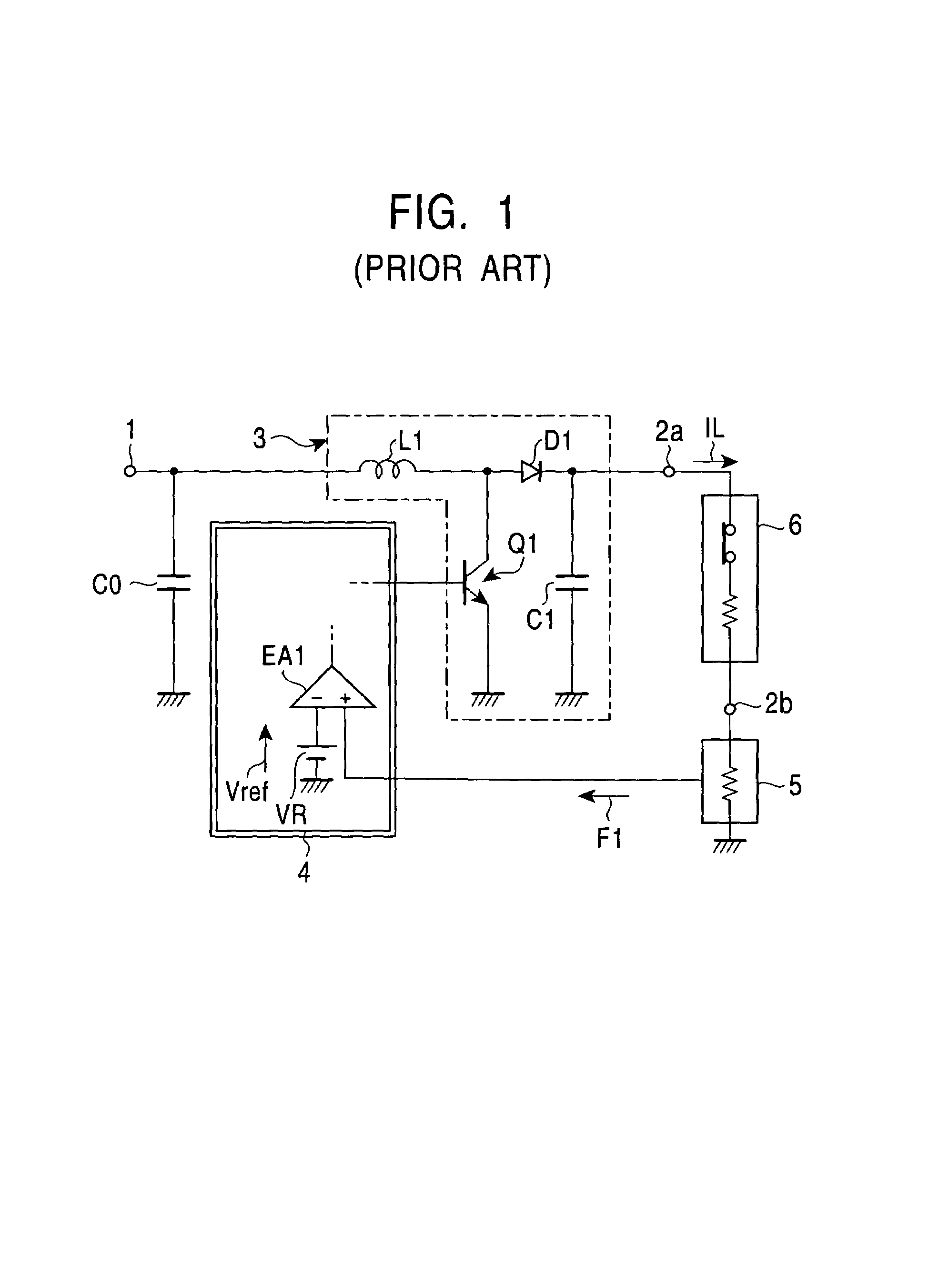
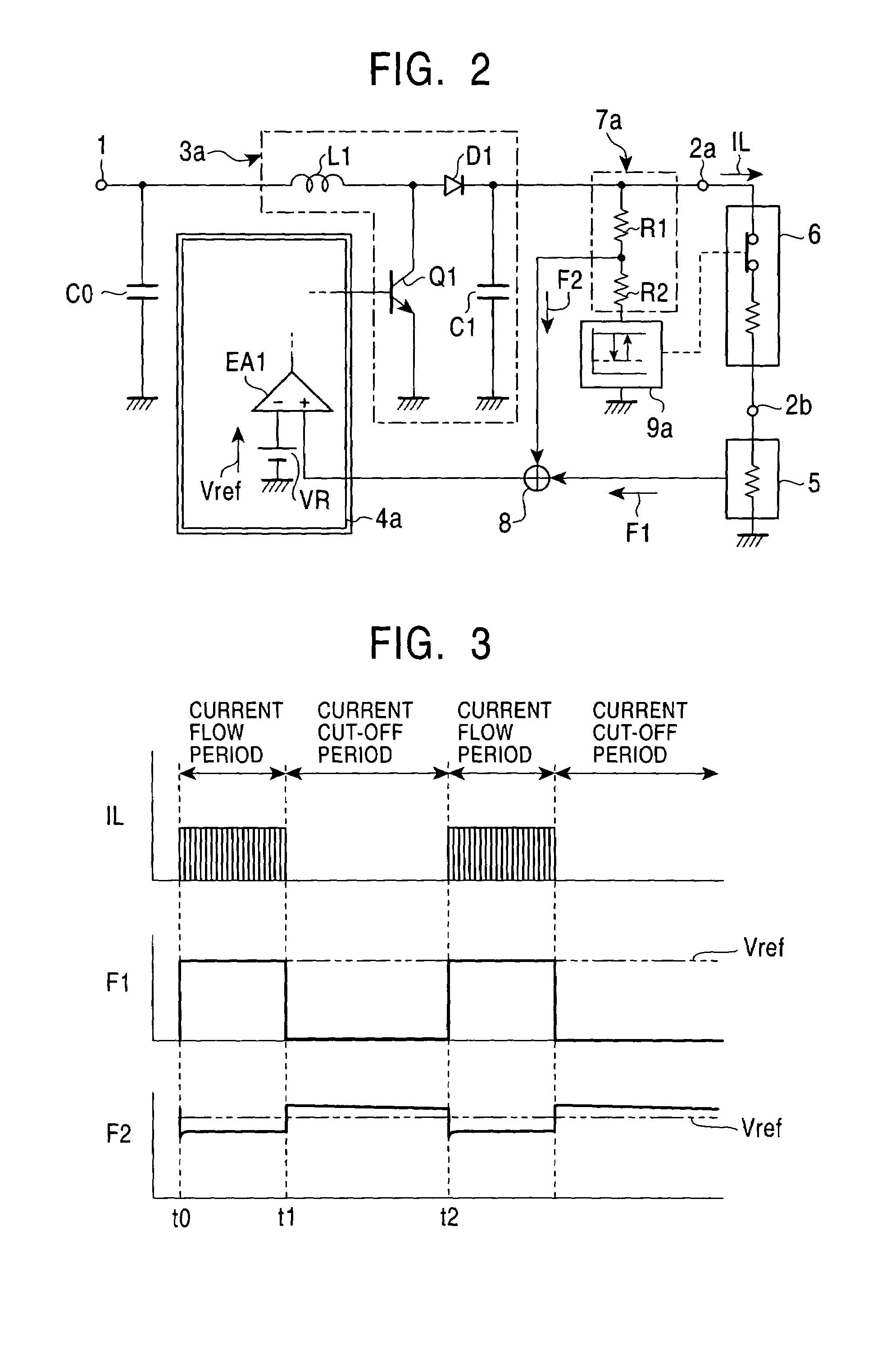
[0042]With reference to the drawings, various embodiments of the present invention will now be described. FIG. 2 is a circuit diagram of a switching-type constant current power supply device according to the present invention. The switching-type constant current power supply device in FIG. 2 comprises a voltage detection circuit 7a and an alteration circuit 9a, which are connected in series with one another between an output terminal 2a and the ground, and a feedback circuit 8 connected between an current detection circuit 5, the voltage detection circuit 7a and a control circuit 4a. The voltage detection circuit 7a is composed of a series circuit of resistors R1 and R2 as with that used in conventional commonly used switching-type power supply devices. Except for the above point, the circuit in FIG. 2 has approximately the same configuration as that of the conventional circuit illustrated in FIG. 1.

[0043]The alteration circuit 9a in FIG. 2 is operable to alter the level of a feedba...

second embodiment

[0056]FIG. 5 is a circuit diagram of a switching-type constant current power supply device according to the present invention. This switching-type constant current power supply device has the following circuit configuration.

[0057]A power conversion circuit 3a including a choke coil L1, a switching transistor Q1, a rectifier diode D1 and a smoothing capacitor C1 which are connected with each other to form a step-up chopper converter is connected between an input terminal 1 and one 2a of a pair of output terminals. A load 6 to be repeatedly turned on and off is connected between the output terminals 2a, 2b, and a current detection circuit 5 is connected the other output terminal 2a and the ground. In this embodiment, the current detection circuit 5 comprises a resistor R4 connected between the output terminal 2b and the ground, an amplifier EA2 having a non-inverting input terminal (+) connected to one of the terminals of the resistor R4 on the side of the output terminal 2b, a resist...

third embodiment

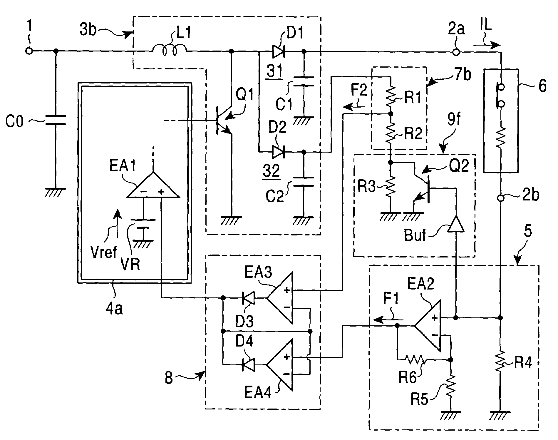
[0069]FIG. 6 is a circuit diagram of a switching-type constant current power supply device according to the present invention. The circuit in FIG. 6 has the following circuit configuration to prevent improper operations due to noises.

[0070]In addition to a first rectifying / smoothing circuit 31 composed of a rectifier diode D1 and a smoothing capacitor C1, a power conversion circuit 3b includes a second rectifying / smoothing circuit 32 composed of a rectifier diode D2 and a smoothing capacitor C2. A voltage detection circuit 7b and an alteration circuit 9e are connected to the second rectifying / smoothing circuit 32 capable of generating an output voltage approximately in conjunction with the output voltage of the first rectifying / smoothing circuit 31. Except for this point, the circuit in FIG. 6 has the same configuration as that of the circuit in FIG. 2.

[0071]The circuit in FIG. 6, which comprises in combination the rectifying / smoothing circuit 31 for supplying current to a load 6 an...


PUM


Abstract

Disclosed is a switching-type constant current power supply, which comprises an alteration circuit 9 provided on the output side of a power conversion circuit 3 together with a voltage detection circuit 7, and a feedback circuit 8 provided between the voltage detection circuit 7, a current detection circuit 5 and a control circuit 4. The alteration circuit 9 is operable, during a current flow period where a load current IL is flowing, to set the signal level of a second feedback signal F2 at a value less than a reference voltage Vref to be supplied to a common error amplifier EA1 in a control circuit 4, and operable, during a current cut-off period where the load current IL is not flowing, to set the signal level of the second feedback signal F2 at a value greater than the reference voltage Vref. During the current cut-off period, the feedback circuit 8 is operable to supply the second feedback signal F2 to the control circuit 4 so as to substantially discontinue the operation of the power conversion circuit 3. The switching-type constant current power supply of the present invention can stabilize the load current even under the condition that a load (e.g. display including LEDs) is repeatedly turned on and off.

Description

TECHNICAL FIELD[0001]The present invention relates to a switching-type constant current power supply device for supplying a stable current to a load which is repeatedly turned on and off.BACKGROUND OF THE INVENTION[0002]Generally, a switching-type power supply device is used as a constant voltage source for supplying a stable voltage to a load. The switching-type power supply device can also be configured as shown in FIG. 1 to allow a feedback signal to be proportional to an output current, so that it can be used as a constant current source for supplying an approximately constant current to a load.[0003]In FIG. 1, the reference numeral 1 indicates an input terminal for receiving power from an external battery, and the reference numerals 2a and 2b indicate a pair of output terminals for stably supplying a given current to a load which is connected therebetween. A power conversion circuit 3 is connected between the input terminal 1 and one 2a of the output terminals. The power conver...

Claims


Application Information

Patent Timeline
Patent Type & Authority Patents(United States)
IPC IPC(8): G05F1/56H02M3/156
CPCH02M3/156H02M2001/0019Y02B70/16H02M2001/0032H02M2001/0025Y02B70/10H02M1/0019H02M1/0025H02M1/0032
Inventor OHTAKE, TETSUSHIOHSUGI, SHIGEYUKI
Owner MURATA MFG CO LTD
Why Eureka
Try Eureka