Power source terminal structure

a technology of power source and terminal, applied in the direction of coupling contact member, coupling device connection, electrical apparatus, etc., can solve the problems of poor contact between the insertion terminal b>, unsteady current, and affected electrical mechanics of associated components, so as to increase the reliability of the connector and ensure the stability of the electric curren

Inactive Publication Date: 2010-10-05
NEXTRONICS ENG CORP
View PDF3 Cites 21 Cited by
  • Summary
  • Abstract
  • Description
  • Claims
  • Application Information

AI Technical Summary

Benefits of technology

[0009]The object of the present invention is to provide a power source terminal structure for Micro Telecommunication Computing Architecture (MicroTCA), thereby increasing the reliability of a connector for transmitting electric current and signals and making the electric current more stable.
[0011]The present invention has advantageous features as follows. The contacting portion of the insertion terminal is provided with a first protrusion. The base of the docking terminal is provided with a second protrusion opposite to the first protrusion and the second protrusion contacts the first protrusion. Via this arrangement, the contact area between the insertion terminal and the docking terminal can be increased, and the reliability of the connector for transmitting the electric current and signals can be increased. Thus, the electric current is more stable.

Problems solved by technology

Furthermore, the quality of associated electronic mechanics will be affected accordingly.
However, when the power source connector is inserted in the docking connector, improper insertion may often cause a poor contact between the insertion terminal 1a and the docking terminal 2a.
Further, any vibration may result in an unsteady current, and thus affects the reliability of transmitting the electric current and signals.

Method used


Image

  • Power source terminal structure
  • Power source terminal structure
  • Power source terminal structure

Examples


Embodiment Construction

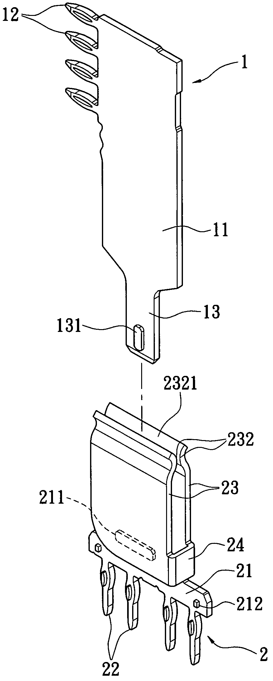
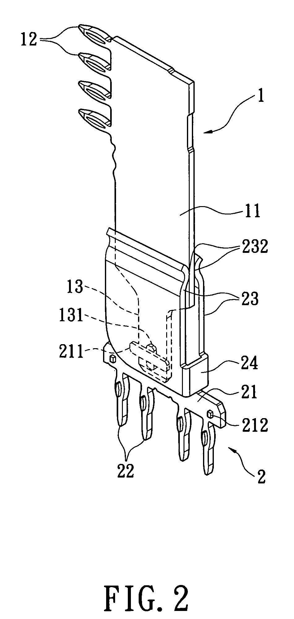
[0019]Please refer to FIGS. 2 to 5. The present invention provides a power source terminal structure. The power source terminal structure is provided in the form of a power source connector and a docking connector (not shown) respectively, and includes an insertion terminal 1 and a docking terminal 2. The insertion terminal 1 is formed into a metal sheet with good electric conductivity, and has a main body 11, a first insertion portion 12 and a contacting portion 13. The main body 11 is formed into an elongate plate. The first insertion portion 12 has a plurality of fish-eye shaped insertion pins that are located on one side of the main body 11. The first insertion portion 12 can be inserted in a power source circuit board (not shown). The contacting portion 13 is formed by extending from one end of the main body 11. In the present embodiment, the contacting portion 13 is provided with a longitudinal first protrusion 131. Of course, a plurality of protrusions can be provided and the...


PUM


Abstract

A power source terminal structure includes an insertion terminal and a docking terminal. The insertion terminal has a main body and a contacting portion. The contacting portion is formed by extending from one end of the main body. The contacting portion is provided with a first protrusion. The docking terminal has a base and two elastic arms. The two elastic arms clamp the main body. The base is provided with a second protrusion opposite perpendicular to the first protrusion. The second protrusion contacts the first protrusion. Via this arrangement, the contact area between the insertion terminal and the docking terminal can be increased, and the reliability of the connector for transmitting the electric current and signals can be increased. Thus, the electric current is more stable.

Description

BACKGROUND OF THE INVENTION[0001]1. Field of the Invention[0002]The present invention relates to a power source terminal structure, and in particular to a power source terminal structure that can be applied to a Micro Telecommunication Computing Architecture (MicroTCA).[0003]2. Description of Related Art[0004]Micro Telecommunication Computing Architecture (referred to as “MicroTCA” hereinafter) is a standard framework for telecommunication grade COTS (Commercial Off-The-Shelf) chassis, which aims to allow Advanced Mezzanine Cards (AMC) to function without any advanced Telecommunications Computing Architecture (AdvancedTCA) carrier card, and the standard is established by PCI Industrial Computer Manufacturer Group (referred to as “PICMG” hereinafter). The standard of MicroTCA is designated PICMG MTCA.X. A common MicroTCA framework is provided therein with at least one controller (Shelf Management Controller, referred to as “ShMC” hereinafter) to execute a Shelf Management Software (r...

Claims


Application Information

Patent Timeline
Patent Type & Authority Patents(United States)
IPC IPC(8): H01R4/48
CPCH01R9/091H01R13/055H01R13/113H01R13/20H01R12/585
Inventor WU, CHIN-PAOYANG, HAI-WEN
Owner NEXTRONICS ENG CORP
Why Eureka
Try Eureka