Advanced synchronous luminescence imaging for chemical and medical diagnostics

a luminescence imaging and synchronous technology, applied in the field of imaging, can solve the problems of not providing the spectral specificity needed to provide clear “spectral fingerprints, providing poorly resolved spectra, and not often providing spectral specificity, so as to improve quantitative measurement accuracy, increase fluorescent signal levels, and improve the effect of overlap

Inactive Publication Date: 2006-09-05
UT BATTELLE LLC
View PDF5 Cites 17 Cited by
  • Summary
  • Abstract
  • Description
  • Claims
  • Application Information

AI Technical Summary

Benefits of technology

[0016]The invention utilizes the wavelength synchronous scanning method, often referred to as synchronous luminescence (SL), operated in a excitation-detection co-registration imaging mode. The use of excitation-detection co-registration provides increased fluorescent signal levels by providing greater overlap of the excitation and emission focal volumes and improved accuracy in quantitative measurements of signal intensity through use of a single optical path for both the excitation and detection signals. As a result, the invention is expected to provide a significant advance in identification of chemical and biological species and an infectious agents in samples as well as disease; to provide earlier detection of a diseased state (e.g cancer) and aid in the understanding and treatment of disease in general.

Problems solved by technology

Although fixed-excitation laser-induced fluorescence (LIF) has been shown to be successful for differentiating normal from malignant tissues, this technique does not distinguish low-grade dysphasia from Barrett's mucosa without dysplasia.
A limitation of the conventional fixed-excitation LIF technique results because it does not often provide the spectral specificity needed to provide clear “spectral fingerprints” of normal and dysplastic tissues mainly because the flourescence of tissue is a composite of fluorescence emissions from various tissue components.
As a result, applied to tissue diagnostics LIF provides spectra that are poorly resolved and featureless because of spectral overlap between the emissions from individual tissue components.
Thus, the laser used in LIF can only improve the sensitivity but cannot enhance the specificity (selectivity).
In addition to spectral specificity problems, current instrumentation for cancer and other tissue diagnostics have other serious limitations.
One major limitation of the conventional fluorescence technique results from the use of a fixed-wavelength excitation source (e.g., a monochromatic laser).
When a single fixed laser line is used, it is difficult, if not impossible, to excite all the biological components under optimal conditions.
As a result, co-registration of the excitation and emission is not possible.
System 100 also does not generally allow precise determination of the emission location as emissions can originate from a plurality of locations around the excitation location.

Method used


Image

  • Advanced synchronous luminescence imaging for chemical and medical diagnostics
  • Advanced synchronous luminescence imaging for chemical and medical diagnostics
  • Advanced synchronous luminescence imaging for chemical and medical diagnostics

Examples


examples

[0097]It should be understood that the examples and embodiments described herein are for illustrative purposes only and that various modifications or changes in light thereof will be suggested to persons skilled in the art and are to be included within the spirit and purview of this application. The invention can take other specific forms without departing from the spirit or essential attributes thereof.

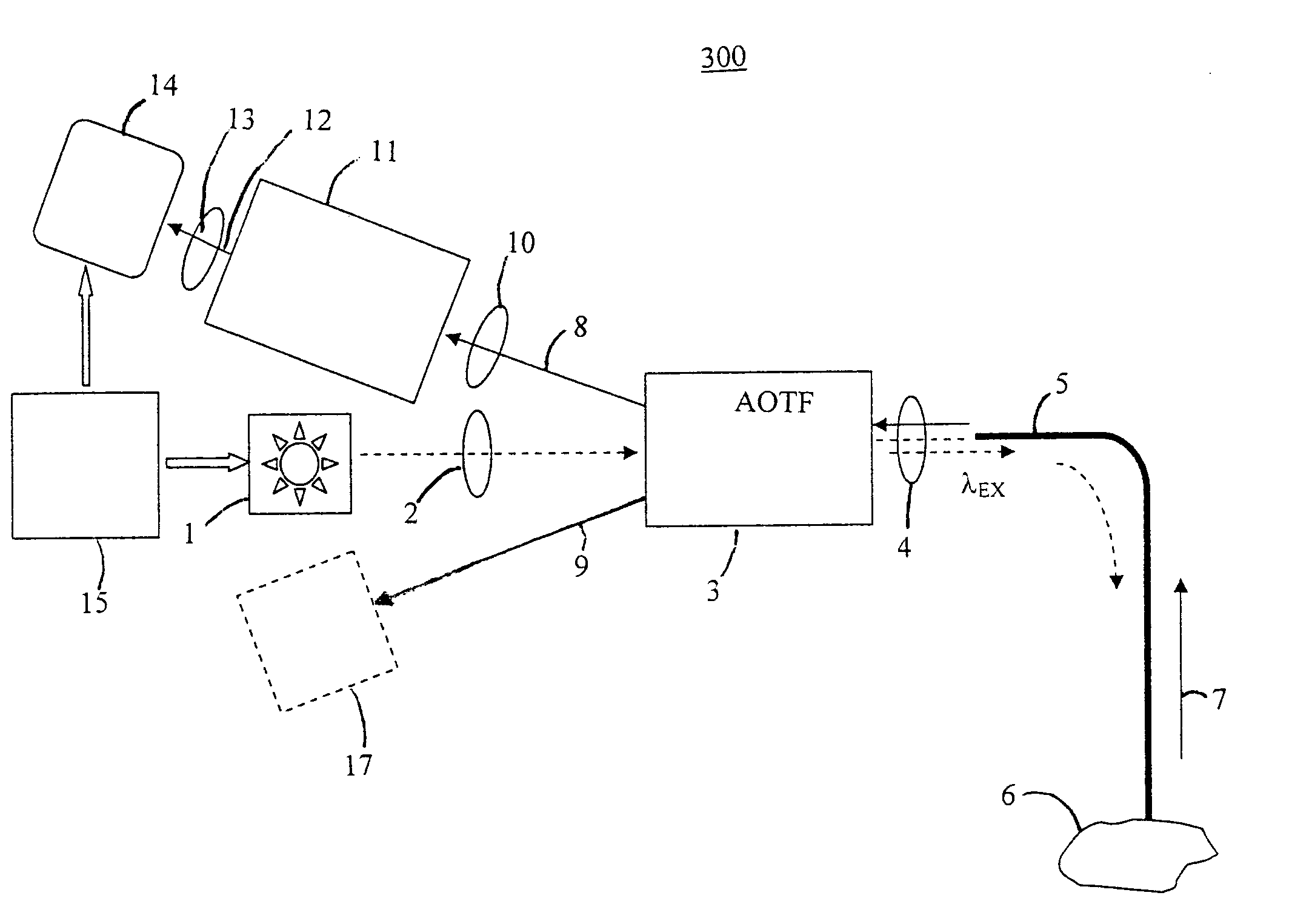
[0098]FIGS. 12A and 12B show examples of reflective and fluorescence imaging results, respectively, obtained from an exemplary AOTF system according to the invention. A subject was provide having a skin surface that included a freckle. The purpose of the demonstration was to determine whether the freckle was cancerous. It is known that cancerous freckles fluoresce differently as compared to non-cancerous freckles and normal skin tissue.

[0099]FIG. 12A shows a recording of the spectral image of the skin surface using excitation at 488 nm. The AOTF (Brimrose) wavelength was also set at ...


PUM

PropertyMeasurementUnit
wavelengthsaaaaaaaaaa
radio frequencyaaaaaaaaaa

Abstract

A diagnostic method and associated system includes the steps of exposing at least one sample location with excitation radiation through a single optical waveguide or a single optical waveguide bundle, wherein the sample emits emission radiation in response to the excitation radiation. The same single optical waveguide or the single optical waveguide bundle receives at least a portion of the emission radiation from the sample, thus providing co-registration of the excitation radiation and the emission radiation. The wavelength of the excitation radiation and emission radiation is synchronously scanned to produce a spectrum upon which an image can be formed. An increased emission signal is generated by the enhanced overlap of the excitation and emission focal volumes provided by co-registration of the excitation and emission signals thus increasing the sensitivity as well as decreasing the exposure time necessary to obtain an image.

Description

STATEMENT REGARDING FEDERALLY SPONSORED RESEARCH OR DEVELOPMENT[0001]The United States Government has rights in this invention pursuant to Contract AC05-00OR22725 between the United States Department of Energy and UT-Battelle, LLC.CROSS-REFERENCE TO RELATED APPLICATIONS[0002]Not applicable.FIELD OF THE INVENTION[0003]The invention relates to imaging, and more particularly to synchronous luminescence imaging for chemical and medical diagnostics.BACKGROUND OF THE INVENTION[0004]Although fixed-excitation laser-induced fluorescence (LIF) has been shown to be successful for differentiating normal from malignant tissues, this technique does not distinguish low-grade dysphasia from Barrett's mucosa without dysplasia. A limitation of the conventional fixed-excitation LIF technique results because it does not often provide the spectral specificity needed to provide clear “spectral fingerprints” of normal and dysplastic tissues mainly because the flourescence of tissue is a composite of fluor...

Claims


Application Information

Patent Timeline
Patent Type & Authority Patents(United States)
IPC IPC(8): A61B5/00G01N21/64
CPCG01N21/6408A61B5/0059
Inventor VO-DINH, TUAN
Owner UT BATTELLE LLC
Why Eureka
Try Eureka