Damper pulley assembly having a safety device

a safety device and pulley technology, applied in the direction of spring/damper design characteristics, couplings, portability lifting, etc., can solve the problems of severe stress on the pulley, serious damage to the vehicle, and inability to guarantee the transmission of the necessary torqu

Inactive Publication Date: 2010-04-22
DAYCO EURO
View PDF3 Cites 25 Cited by
  • Summary
  • Abstract
  • Description
  • Claims
  • Application Information

AI Technical Summary

Benefits of technology

[0008]It is an object of the present invention to provide a damper pulley assembly designed to eliminate the aforementioned drawback.

Problems solved by technology

Because of the increase in power absorption by the accessory devices driven by the accessory drive, the pulley is now subjected to severer stress than in the past.
When power absorption exceeds a given threshold, an elastomeric ring cannot guarantee transmission of the necessary torque, and is therefore replaced with a metal spring.
Moreover, failure of the elastic member of a damper pulley assembly may arrest operation of the accessory drive and so endanger passengers and result in serious damage to the vehicle.

Method used


Image

  • Damper pulley assembly having a safety device
  • Damper pulley assembly having a safety device
  • Damper pulley assembly having a safety device

Examples


Embodiment Construction

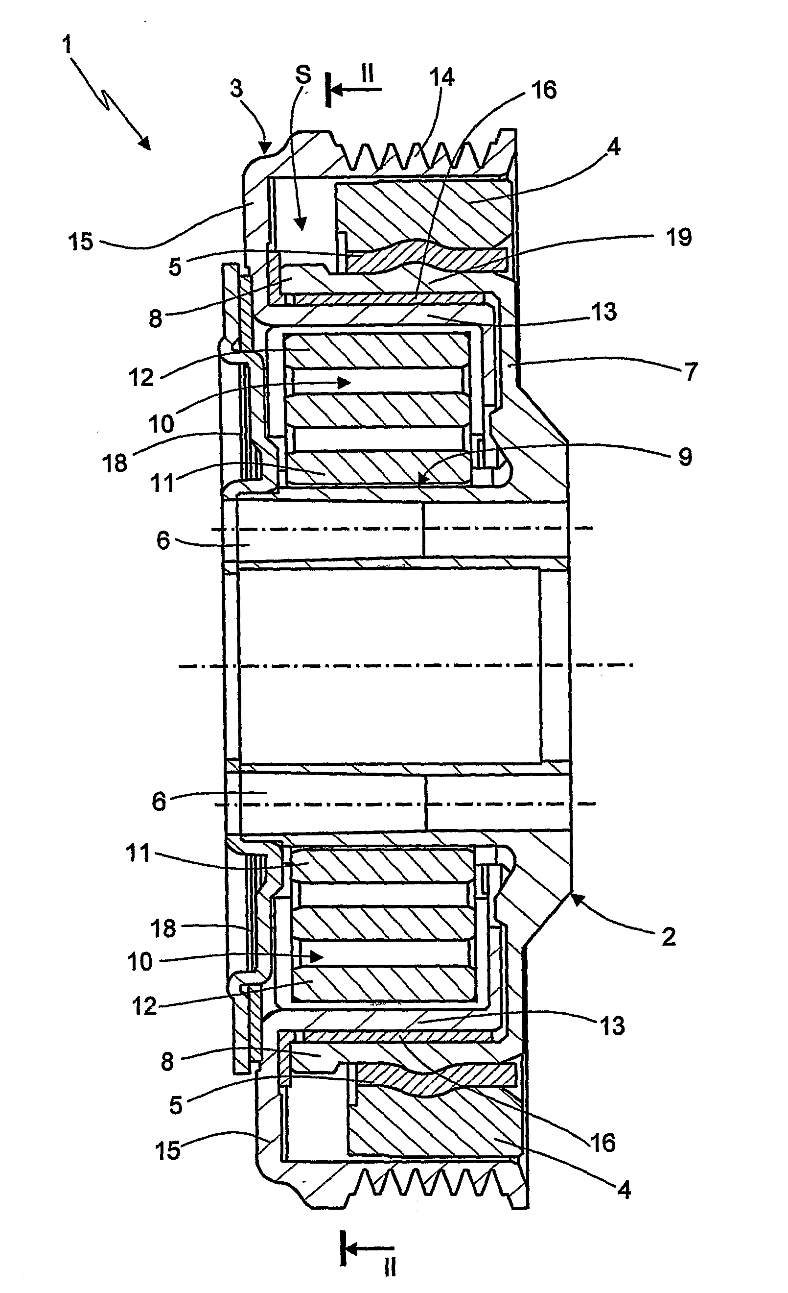
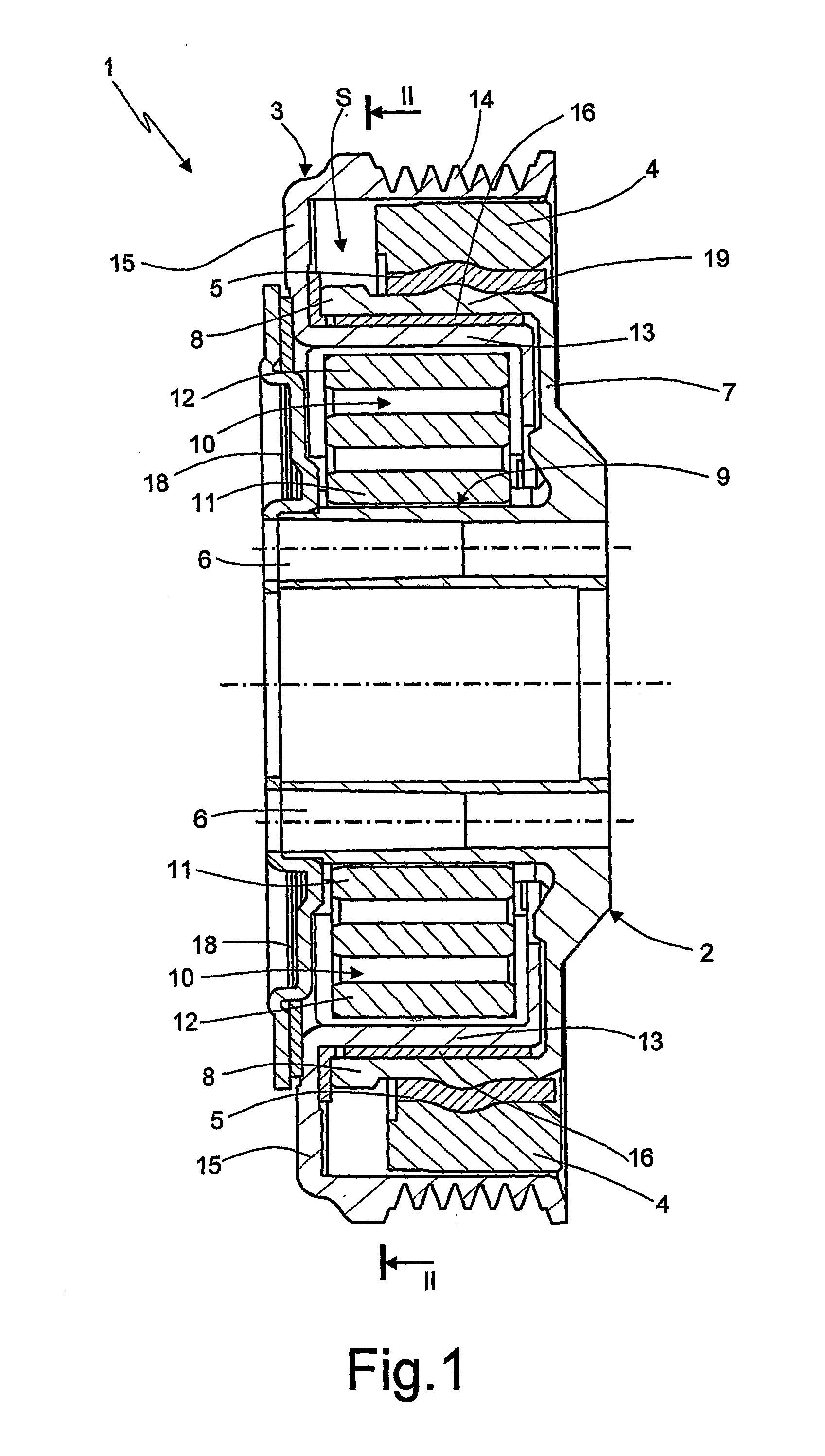
[0014]Number 1 in FIG. 1 indicates as a whole, a damper pulley assembly comprising a hub 2 connected rigidly to a crankshaft; an annular pulley 3 supported by hub 2; and a seismic mass 4 connected to hub 2 by a band 5 of elastomeric material to define a dynamic torsional vibration damper.

[0015]More specifically, hub 2 comprises a tubular portion having an axis A; a wall 7 extending from tubular portion 6; and a cylindrical wall 8 concentric with tubular portion 6.

[0016]More specifically, tubular portion 6, wall 7, and cylindrical wall 8 are arranged to define a C-shaped section and a corresponding cavity 9.

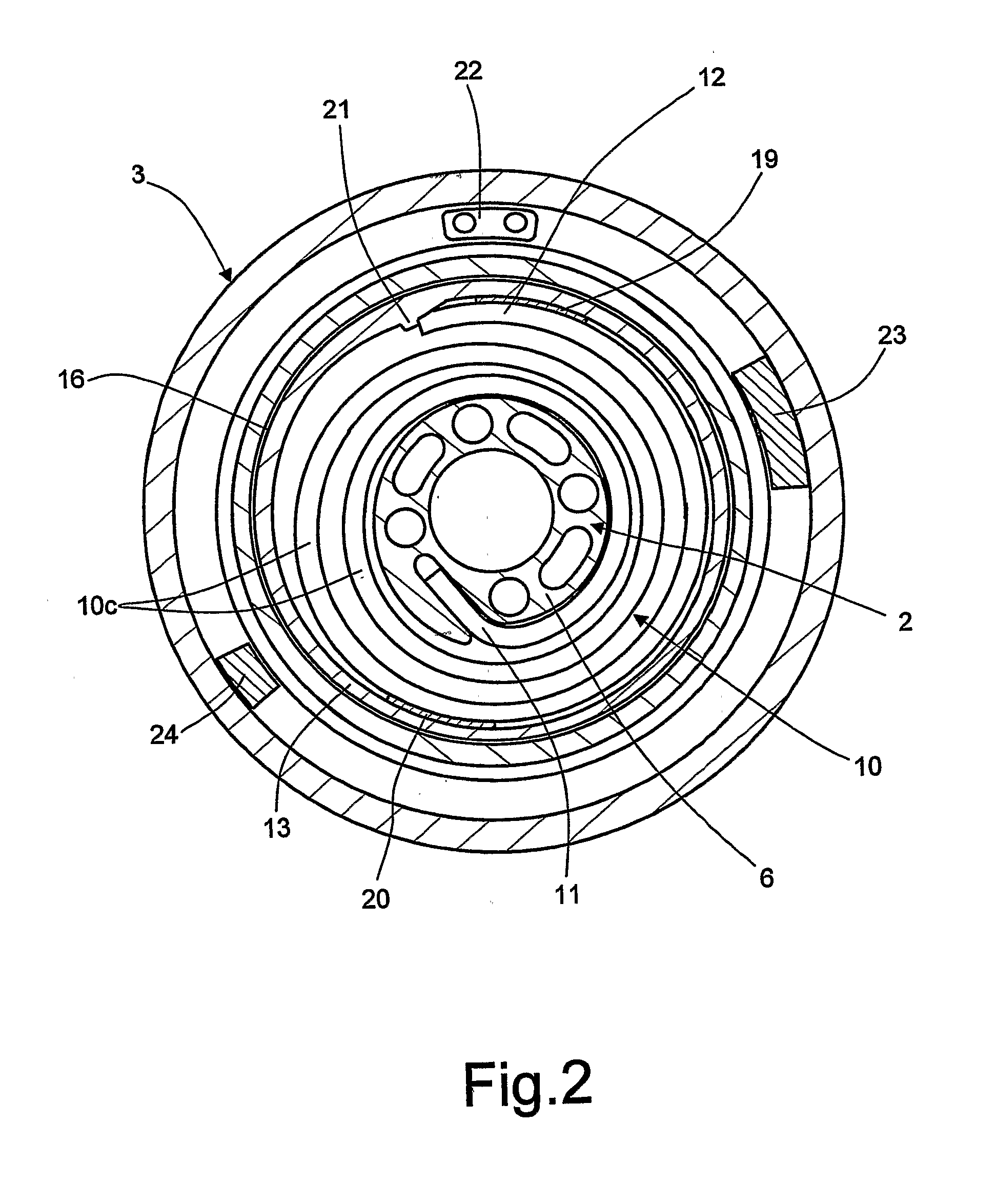
[0017]Cavity 9 houses an elastic member, preferably metal spiral spring 10, comprising an end portion 11 connected rigidly to tubular portion 6; a free end portion 12 connected frictionally to pulley 3; and a number of turns 10c interposed between end portions 11 and 12.

[0018]Pulley 3 has a C-shaped cross section, and comprises a cylindrical wall 13 interposed radially between end...


PUM


Abstract

A damper pulley assembly has a hub; a seismic mass connected to the hub to define a dynamic torsional vibration damper; a pulley connected to the hub; elastic means for connecting the pulley in torque-transmitting mode to the hub; and one-way stop means for arresting the pulley in a first stop position with respect to the hub or the seismic mass in a first direction, when the elastic means reach a predetermined torsional load.

Description

TECHNICAL FIELD[0001]The present invention relates to a damper pulley assembly having a safety device and preferably fitted to an internal combustion engine crankshaft to control the accessory device drive of a motor vehicle.BACKGROUND ART[0002]A damper pulley assembly normally comprises a hub connected rigidly to an internal combustion engine crankshaft; a pulley connected to the hub; and a seismic mass connected to the hub to define a dynamic torsional vibration damper.[0003]More specifically, the pulley is connected, to rotate with respect to the hub, by an elastic member interposed between the pulley and the hub. The most commonly used elastic members are a ring of elastomeric material, or one or more metal spiral or helical springs.[0004]Because of the increase in power absorption by the accessory devices driven by the accessory drive, the pulley is now subjected to severer stress than in the past.[0005]When power absorption exceeds a given threshold, an elastomeric ring cannot...

Claims


Application Information

Patent Timeline
Patent Type & Authority Applications(United States)
IPC IPC(8): F16H55/36
CPCF16F15/1442F16H2055/366F16H55/36F16F2230/007F16F15/123F16F15/129F16H55/14
Inventor ROLANDO, ADRIANORIU, HERVE
Owner DAYCO EURO
Why Eureka
Try Eureka