Print status monitor control for printing devices on network

a network and status monitor technology, applied in the direction of digital output to print units, instruments, computing, etc., can solve the problems of heavy network traffic, inability of management servers to effectively monitor momentarily changing print status, and the proposed structure still has a problem, so as to reduce the potential for heavy network traffic

Inactive Publication Date: 2006-08-31
SEIKO EPSON CORP
View PDF7 Cites 79 Cited by
  • Summary
  • Abstract
  • Description
  • Claims
  • Application Information

AI Technical Summary

Benefits of technology

[0139] In the device management system 1000 of the embodiment described above, the management server SV as the print request sender sends a print job file, which specifies a print job to be executed, over the firewall FW to the printer PRT1 as the printing destination printer. Prior to a start of monitoring the status of the print job, the management server SV sends the polling interval reduction request information at the polling timing of the printer PRT1 to change the polling interval of the printer PRT1 from the normal polling interval to the shorter polling interval.
[0140] The management server SV sends the print status upload request information, as a request for sending (uploading) the print status information representing the status of the print job (print status), to the printer PRT1 at every polling timing of the printer PRT1 corresponding to the shorter polling interval. In response to the print status upload request, the printer PRT1 obtains the print status information of the print job and sends back (uploads) the obtained print status information to the management server SV. The printer PRT1 works as the distribution source printer and distributes the print job data to the three printers PRT1 to PRT3 specified as the distribution destination printers for distributed printing. The printer PRT1 as the printing destination printer thus collectively obtains the print status

Problems solved by technology

This structure may interfere with the management server-based operations to send a transmission request of the monitor information to the device and obtain the monitor information from the device in response to the transmission request.
This proposed structure, however, still has a problem.
Heavy network traffic may be caused by

Method used


Image

  • Print status monitor control for printing devices on network
  • Print status monitor control for printing devices on network
  • Print status monitor control for printing devices on network

Examples


embodiment

A. Embodiment

A1. Configuration of Device Management System

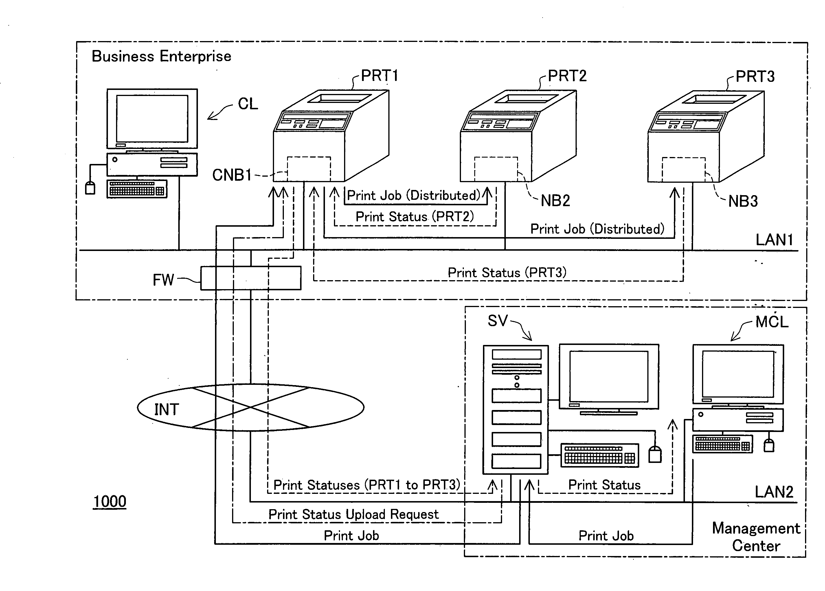
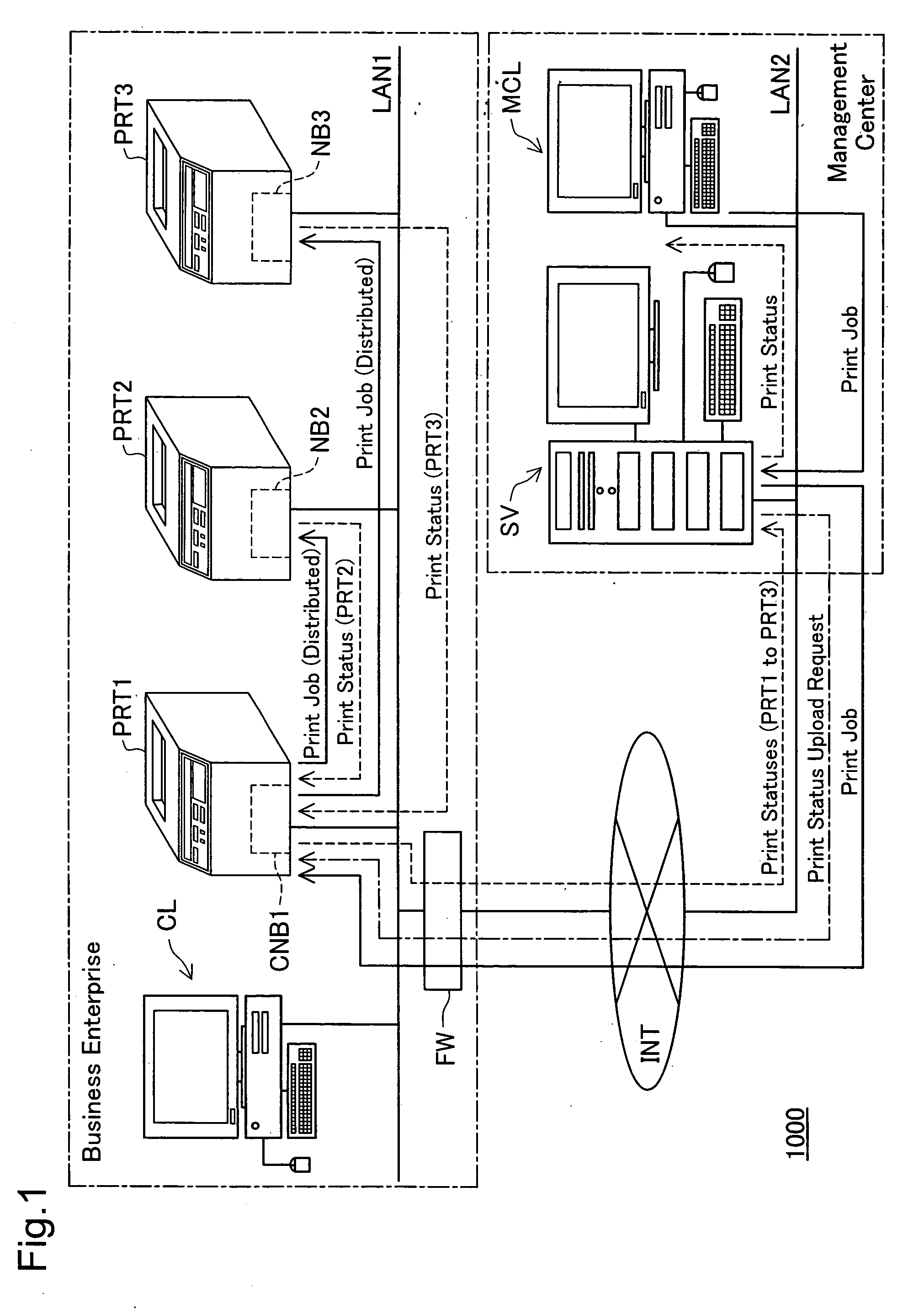
[0047]FIG. 1 schematically illustrates the configuration of a device management system 1000 in one embodiment of the invention. In the device management system 1000 of the embodiment, a local area network LAN1 constructed in an organization, for example, a business enterprise (hereafter referred to as in-company local area network LAN1), is connected to a local area network LAN2 constructed in a management center (hereafter referred to as in-management center local area network LAN2) via the Internet INT. A management server SV linked to the in-management center local area network LAN2 is accordingly connected with the in-company local area network LAN1.

[0048] A firewall FW is placed between the in-company local area network LAN1 and the Internet INT to prohibit external accesses from the Internet INT to the in-company local area network LAN1.

[0049] In the illustrated example of FIG. 1, only one in-company local area netw...

modified example 1

B1. Modified Example 1

[0144] The print status monitor process of the embodiment is applied to distributed printing where the printer PRT1 is specified as the printing destination printer and as the distribution source printer and the three printers PRT1 to PRT3 are specified as the distribution destination printers and as the printing execution printers. The printer PRT1 specified as the printing destination printer collectively obtains the print statues of the printers PRT1 to PRT3 as the printing execution printers and sends (uploads) the obtained print statuses as the print status information in response to a print status upload request from the management server SV. This application is, however, not restrictive. The print status monitoring technique of the invention is also applicable to ordinary printing with only the printer PRT1 specified as the printing destination printer and as the printing execution printer. The printer PRT1 as the printing destination printer sends (uplo...

modified example 2

B2. Modified Example 2

[0145] In the device management system 1000 of the embodiment described above, only the printer PRT1 has the built-in print status monitor control apparatus of the invention. All or any part of multiple printers on a LAN may have the built-in print status monitor control apparatus of the invention.


PUM


Abstract

In a print status monitor system of the invention, a specified printer receives a polling interval reduction request from a server in response to polling made at a normal polling interval set to a polling interval, and changes the polling interval to a shorter polling interval, which is shorter than the normal polling interval. The server sends a print status transmission request to the specified printer, in response to polling made by the specified printer at the shorter polling interval. The specified printer receives the print status transmission request sent from the server in response to the polling made to the server at the shorter polling interval, obtains print status information representing the status of a print job, and sends the obtained print status information to the server. The server receives and obtains the print status information sent from the specified printer in response to the print status transmission request. This arrangement enables the server to monitor the status of a print job sent to a printer under management of the server, while reducing the potential for heavy network traffic.

Description

BACKGROUND OF THE INVENTION [0001] 1. Field of the Invention [0002] The present invention relates to a technique of monitoring the status of printing in printers on a network. [0003] 2. Description of the Related Art [0004] With the recent advance of the network technology relating to the Internet and local area networks, device management systems have been proposed, in which multiple devices, such as printers, on a network are managed by a management server connected to the multiple devices via the network (see, for example, Japanese Patent Laid-Open Gazette No. 2004-185351 and No. 2002-189638). In the proposed device management system, each device connected to the network has a built-in network board to obtain predetermined monitor information regarding the device, for example, the operation state of the device, and sends the obtained monitor information to the management server. The monitor information obtained by monitoring a printer as the device includes, for example, the numb...

Claims


Application Information

Patent Timeline
IPC IPC(8): G06F3/12
CPCG06F3/1204G06F3/126G06F3/1286G06F3/1259G06F3/1288
Inventor MATSUMOTO, AKIRASHIMA, TOSHIHIRO
Owner SEIKO EPSON CORP
Why Eureka
Try Eureka