Electrophoretic display and novel process for its manufacture

a technology of electrophoretic display and microencapsulation process, which is applied in the direction of electrographic process, static indicating device, instruments, etc., can solve the problems of difficult to keep different colors of suspensions from each other in the partition-type electrophoretic display, and the electrophoretic display manufactured by the microencapsulation process suffers from sensitivity to environmental changes

Inactive Publication Date: 2004-12-21
E INK CALIFORNIA
View PDF113 Cites 79 Cited by
  • Summary
  • Abstract
  • Description
  • Claims
  • Application Information

AI Technical Summary

Problems solved by technology

However, in the case of partition-type electrophoretic displays, some difficulties were encountered in the formation of the partitions and the process of enclosing the suspension.
Furthermore, it was also difficult to keep different colors of suspensions separate from each other in the partition-type electrophoretic display.
For example, the electrophoretic display manufactured by the microencapsulation process suffers from sensitivity to environmental changes (in particular sensitivity to moisture and temperature) due to the wall chemistry of the microcapsules.
Secondly the electrophoretic display based on the microcapsules has poor scratch resistance due to the thin wall and large particle size of the microcapsules.
To improve the handleability of the display, microcapsules are embedded in a large quantity of polymer matrix which results in a slow response time due to the large distance between the two electrodes and a low contrast ratio due to the low payload of pigment particles.
It is also difficult to increase the surface charge density on the pigment particles because charge-controlling agents tend to diffuse to the water / oil interface during the microencapsulation process.
The low charge density or zeta potential of the pigment particles in the microcapsules also results in a slow response rate.
Furthermore, because of the large particle size and broad size distribution of the microcapsules, the prior art electrophoretic display of this type has poor resolution and addressability for color applications.
The display fluid within a conventional display prepared by the edge sealing adhesive method will leak out completely if the display is cut in any way, or if a hole is drilled through the display.
The damaged display will be no longer functional.
Without the microcup structure, it will be very difficult to prevent the fluids in adjacent areas from intermixing or being subject to cross-talk during operation.

Method used


Image

  • Electrophoretic display and novel process for its manufacture
  • Electrophoretic display and novel process for its manufacture
  • Electrophoretic display and novel process for its manufacture

Examples


example 1

Preparation of Microcups by Microembossing

The composition shown in Table 1 was coated onto Mylar.TM. J101 / 200 gauge using a Nickel Chrome bird type film applicator with an opening of 3 mil. The solvent was allowed to evaporate leaving behind a tacky film with a Tg below room temperature.

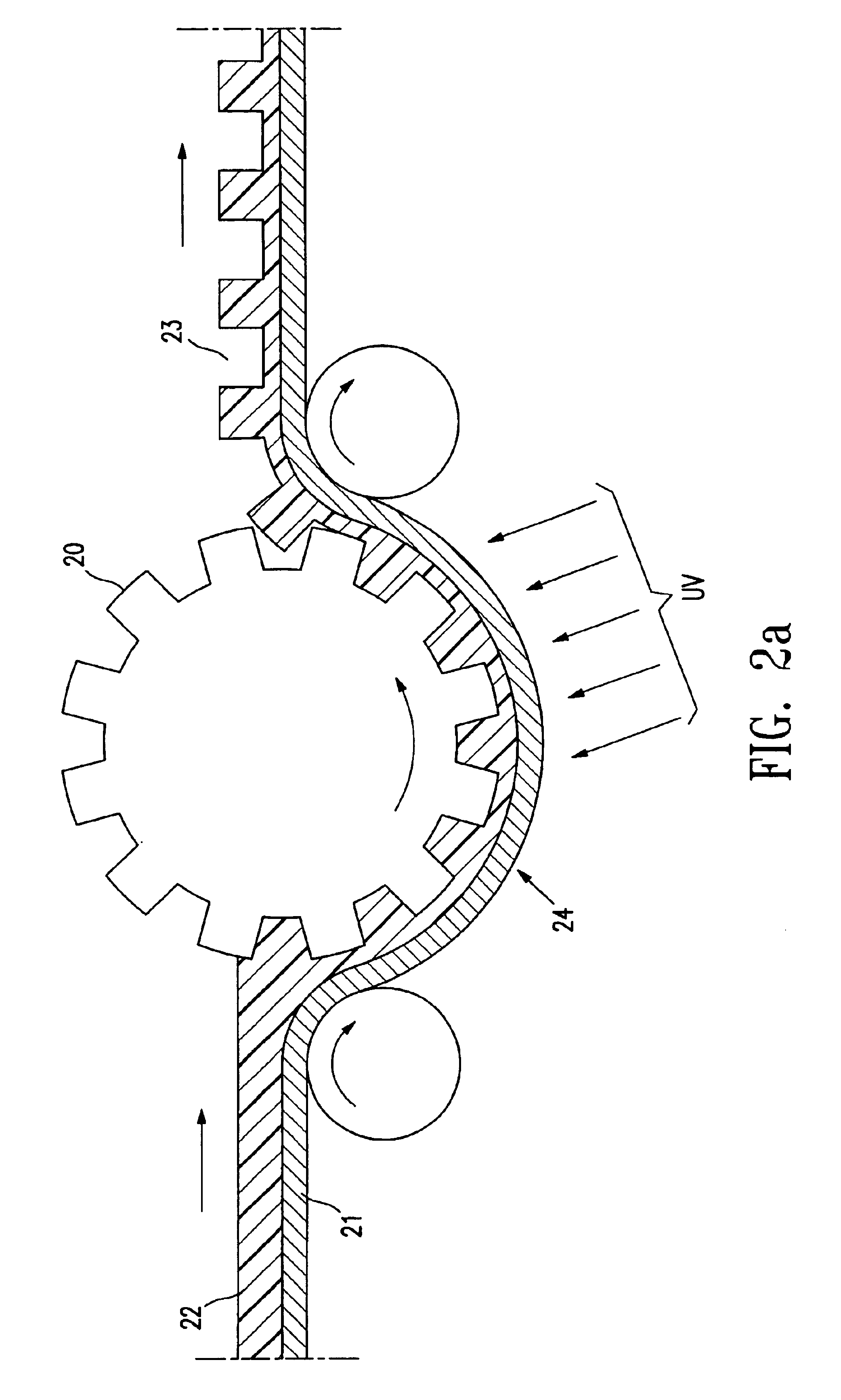
A pre-patterned stencil from Photo Stencil, Colorado Springs, Colo., was used as the male mold for microembossing and Frekote.TM. 700-NC from Henkel was used as the mold release. The coated film was then embossed by the stencil using a pressure roller at room temperature. The coating was then UV cured for about 20 minutes through the Mylar.TM. film using a Loctite Zeta 7410.TM. exposure unit equipped with a metal fluoride lamp with an intensity of 80 mW / cm.sup.2 at 365 nm. The embossed film was then released from the mold to reveal well-defined microcups having lateral dimensions ranging from 60 .mu.m to 120 .mu.m (200-400 dpi) and a depth ranging from 5 .mu.m to 30 .mu.m as measured by optical profi...

example 2

Preparation of Microcups

A composition containing solid oligomer, monomer and additive is shown in Table 2. The glass transition temperature of the mixture is again below room temperature. The tacky coating was deposited on top of Mylar.TM. J101 / 200 gauge as before. Embossing was conducted at 60.degree. C. using a heated pressure roller or laminator. Well-defined high resolution microcups (100-400 dpi) with depth ranging from 5-30 microns were produced.

example 3

Preparation of Pigment Dispersion in Dielectric Solvent

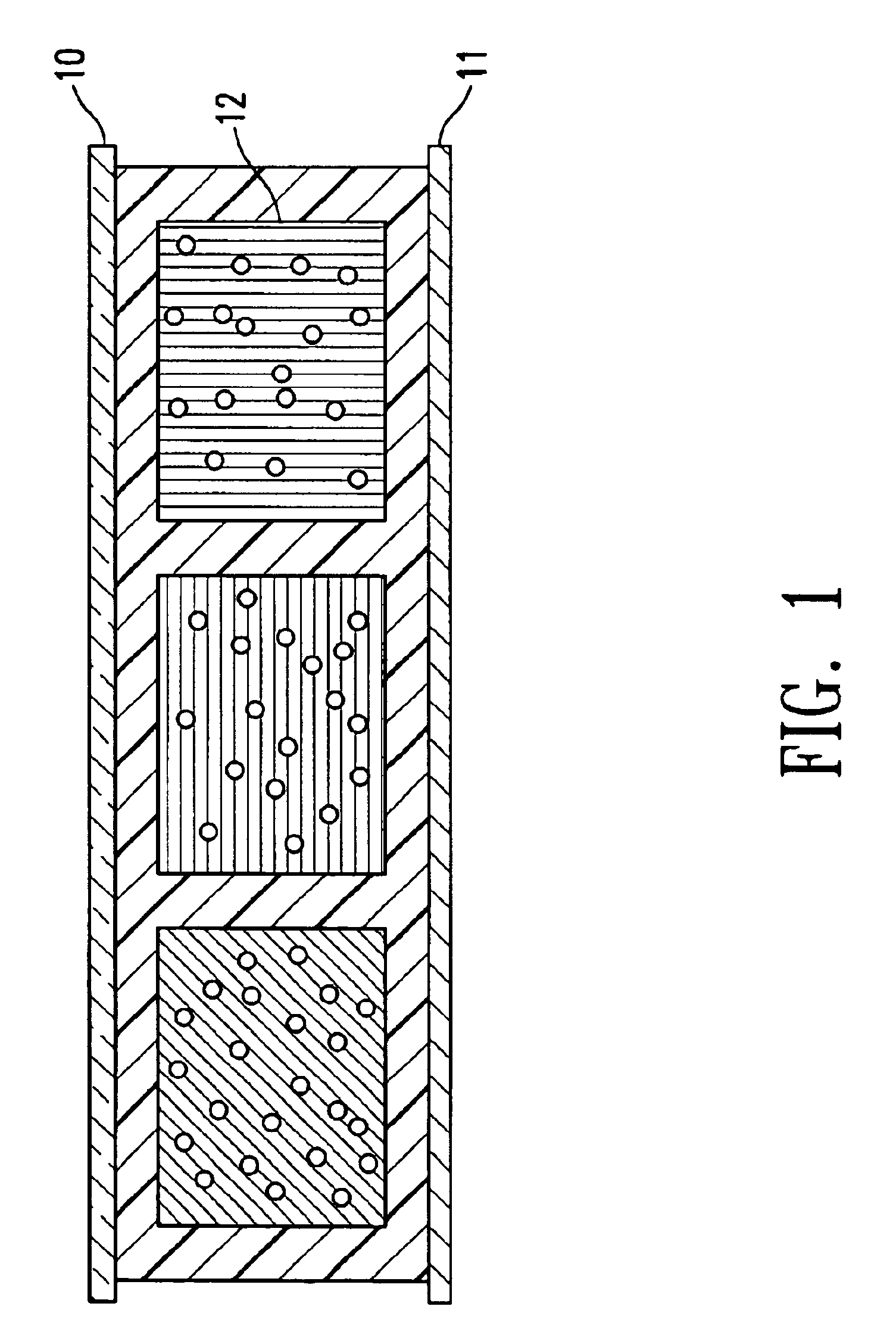
Polystyrene (0.89 grams, Polysciences, Inc., mw. 50,000) and AOT (0.094 grams, American Cyanamide, sodium dioctylsulfosuccinate) were dissolved in 17.77 grams of hot xylene (Aldrich). Ti-Pure R-706.TM. (6.25 grams) was added to the solution and ground in an attritor at 200 rpm for more than 12 hours. A low viscosity, stable dispersion was obtained. Oil-blue N (0.25 grams, Aldrich) was added to color the dispersion. The suspension was then tested in a standard electrophoretic cell comprising two ITO conductor plates separated by a 24 microns spacer. High contrast, alternating white and blue images were observed with a switching rate of about 60 Hz and a rising time of 8.5 msec at 80 volts.


PUM

PropertyMeasurementUnit
temperatureaaaaaaaaaa
thickaaaaaaaaaa

Abstract

This invention relates to an electrophoretic display comprising cells which are filled with charged particles dispersed in a solvent and are individually sealed with a polymeric sealing layer which is an integral part of the display and is curved.

Description

Field of the InventionDESCRIPTION OF RELATED ARTThe electrophoretic display is a non-emissive device based on the electrophoresis phenomenon of charged pigment particles suspended in a solvent. It was first proposed in 1969. The display usually comprises two plates with electrodes placed opposing each other, separated by using spacers. One of the electrodes is usually transparent. A suspension composed of a colored solvent and charged pigment particles is enclosed between the two plates. When a voltage difference is imposed between the two electrodes, the pigment particles migrate to one side and then either the color of the pigment or the color of the solvent can be seen according to the polarity of the voltage difference.In order to prevent undesired movement of the particles, such as sedimentation, partitions between the two electrodes were proposed for dividing the space into smaller cells. However, in the case of partition-type electrophoretic displays, some difficulties were e...

Claims


Application Information

Patent Timeline
Patent Type & Authority Patents(United States)
IPC IPC(8): G02F1/01G02F1/167G02F1/1339G02F1/1333G02F1/13G01N27/447G02F1/1679
CPCG02F1/167G02F1/133305G02F1/1339G02F1/133377G02F1/1679
Inventor LIANG, RONG-CHANGTSENG, SCOTT C. J.WU, ZARNG-ARH GEORGEZANG, HONGMEI
Owner E INK CALIFORNIA
Why Eureka
Try Eureka