Cover assembly for an electrical box

a technology for electrical boxes and covers, applied in the direction of hinges, manufacturing tools, coupling device connections, etc., can solve the problems of difficult visual inspection of the latched cover, requiring additional parts and assembly time, and complicating manufacturing, so as to prevent deflection of the pin, reduce manufacturing costs, and facilitate assembly

Inactive Publication Date: 2005-01-11
THOMAS & BETTS INT INC
View PDF37 Cites 47 Cited by
  • Summary
  • Abstract
  • Description
  • Claims
  • Application Information

AI Technical Summary

Benefits of technology

It is an advantage of the present invention to provide a cover assembly for an electrical box
It is another advantage of the present invention to provide a cover assembly for an electrical floor box.
It is a further advantage of the present invention to provide a cover assembly for an electrical floor box having a cover that is easily secured in the closed position and cost efficient to manufacture.
It is still a further advantage of the present invention to provide an electrical floor box having a cover pivotally connected to a frame by a hinge. The hinge permits both rotational and translational movement of the cover relative to the frame. The hinge includes a biasing means for urging the cover into a latched position when the cover is in a closed position.
It is yet a further advantage of the present invention to provide a hinge for an electrical box cover including a cover and frame having a resilient elongate pin supported at each end thereof on either the cover or the frame. A pin retainer is positionable over the pin and the retainer is attachable to either the cover or the frame. The retainer includes a first section for preventing deflection of the pin and a second section configured to permit deflection of the pin. The hinge permits rotation and translation of the cover relative to the frame.

Problems solved by technology

This type of cover may be moved into the closed position but not secured, making it difficult to determine for visual inspection if the cover is latched.
Both the screw on cover and screw fastener covers require time to secure the cover and also require the use of a tool.
Such clasps are often separate elements which must be secured to the cover, thereby requiring additional parts and assembly time thereby complicating manufacturing.

Method used


Image

  • Cover assembly for an electrical box
  • Cover assembly for an electrical box
  • Cover assembly for an electrical box

Examples


Embodiment Construction

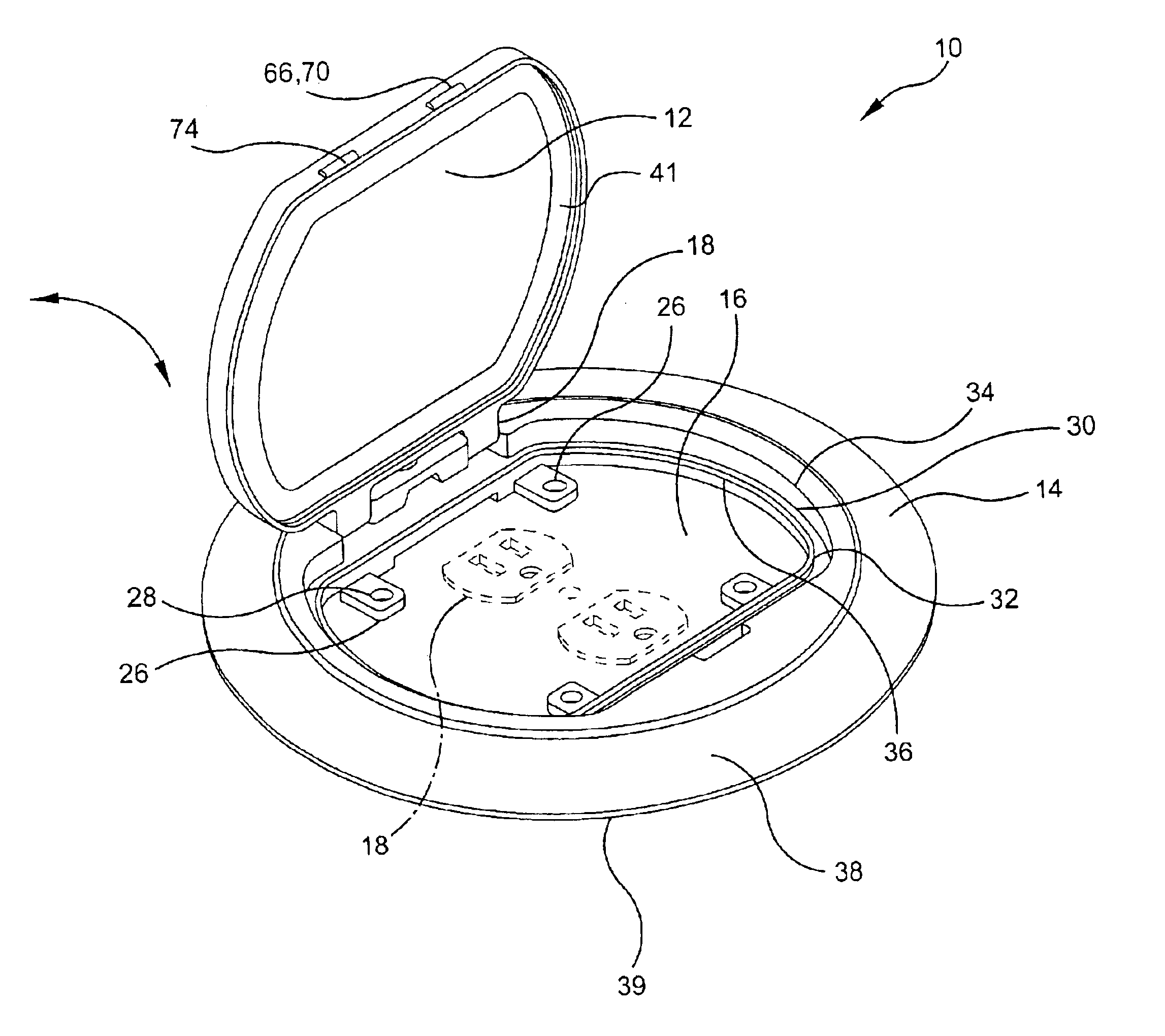
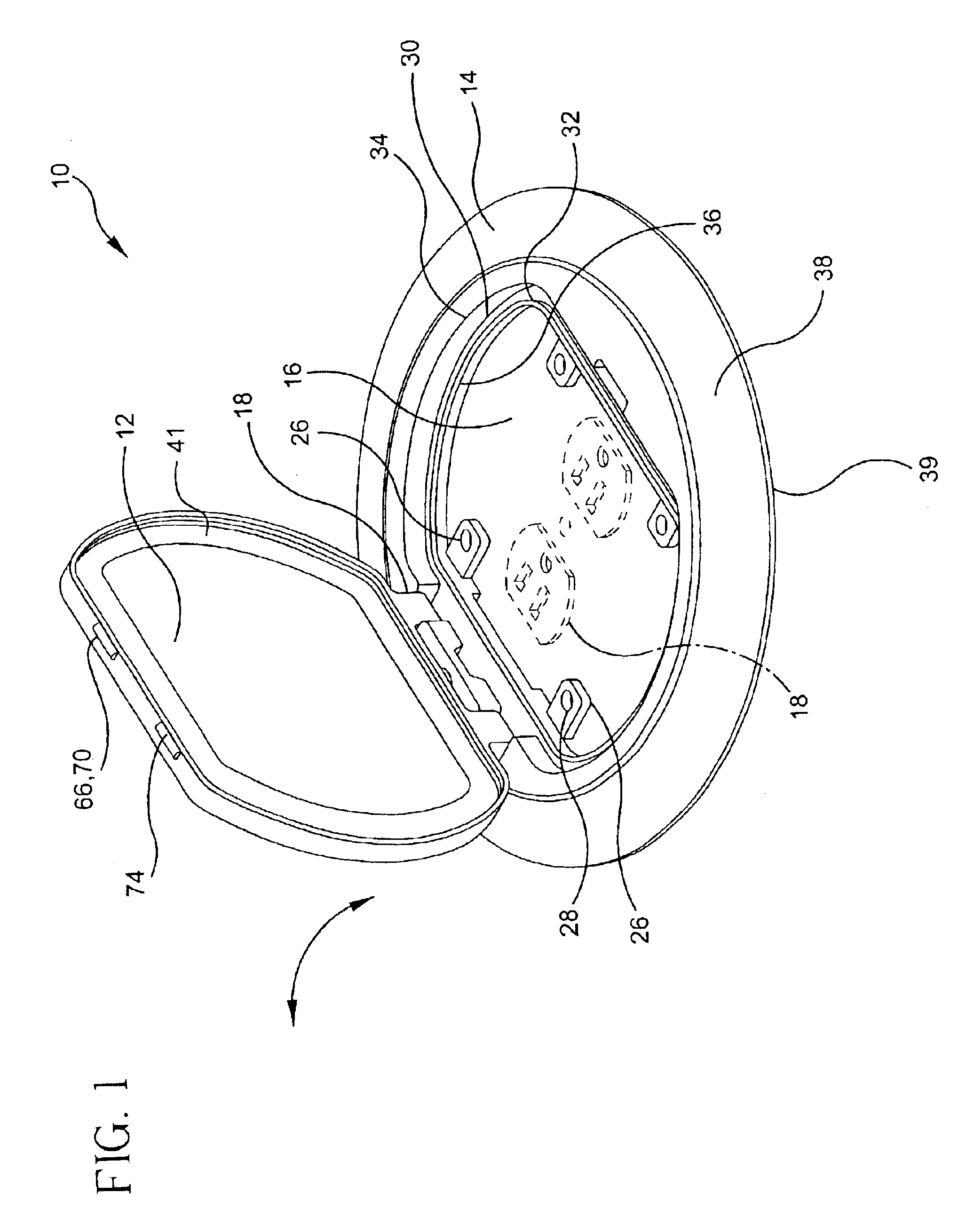
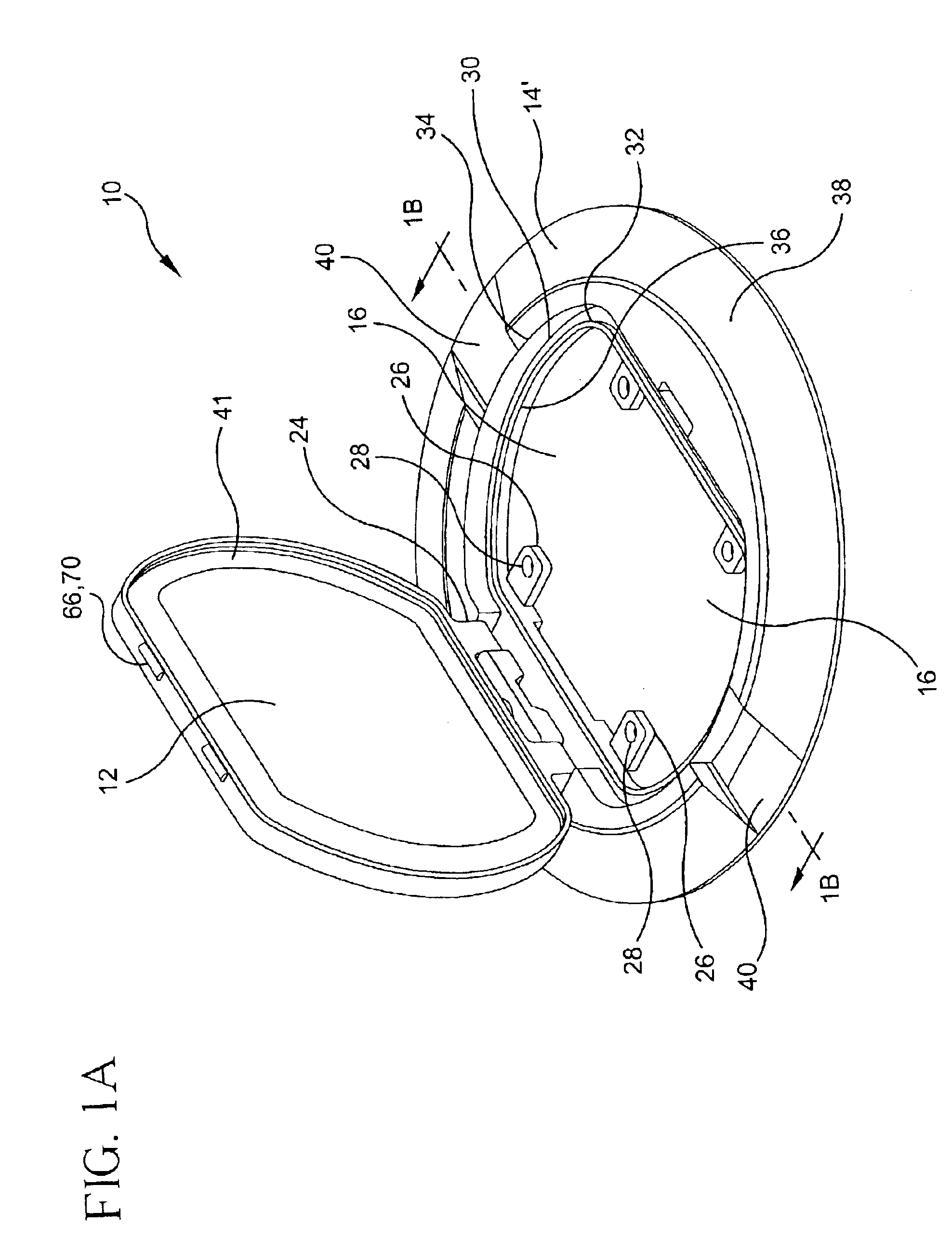
The present invention provides an electrical box cover assembly which is positionable on top of an electrical box. The cover assembly is particularly suited for use with an electrical box disposed in a floor. The electrical box may include connections for power or voice / data devices as is well known in the art. The electrical box cover assembly includes a cover which is easily securable in the closed position and securely held therein. While electrical box cover assembly is described herein on a floor box application, it is within the contemplation of the present invention that cover assembly 10 may be used on a wide variety of electrical boxes and other applications where a cover that can be selectively opened is desired.

With reference to FIGS. 1, and 2-4, electrical box cover assembly 10 includes a cover 12 which is securable to frame 14. Frame 14 has an opening 16 that is selectively positionable over an electrical box 20. Cover 12 is movable between an open and closed position t...


PUM


Abstract

A cover assembly for an electrical box including a frame having an opening positionable over the electrical box and a cover selectively positionable over the opening and rotatable between a closed position and an open position. A hinge rotatably secures the cover to the frame and permits rotational and translational movement of the cover relative to the frame. The hinge includes a biasing device for urging the cover toward a first translational direction. A latch including a locking element is disposed between the cover and the frame for retaining the cover in the closed position. The biasing device deflects upon movement of the cover into the closed position and urges the locking element into a retaining position such that the locking element restricts movement of the cover to the open position.

Description

FIELD OF INVENTIONThe present invention relates to a cover assembly for an electrical box and more specifically to a cover assembly for an electrical floor box having a cover which is easily and securely held in the closed position.BACKGROUND OF THE INVENTIONIn office space and other commercial environments it is often desirable to have access to electrical outlets or other electrical connections at locations located a distance from standard wall outlets. In order to safely accommodate such situations, floor boxes are typically used. These electrical boxes may be located in the floor near or at the location, such as under a work cubicle or near a piece of machinery, where the connection is needed. The electrical connections may be electrical outlets, telephone jacks or data connections used for networking computers.Floor boxes may include a flange which sits on top of the floor surface and includes an opening to permit access to the electrical connections. A cover is typically remov...

Claims


Application Information

Patent Timeline
Patent Type & Authority Patents(United States)
IPC IPC(8): H01R13/52
CPCH01R13/5213Y10T16/554
Inventor DRANE, MARK R.
Owner THOMAS & BETTS INT INC
Why Eureka
Try Eureka