Optical fiber connector

a technology fiber optic cables, applied in the field of optical fiber connectors, can solve problems such as difficult metal latch design and construction, particularly challenging tasks, and metal housings that are difficult to meet the needs of us

Active Publication Date: 2012-08-23
MOLEX INC
View PDF6 Cites 51 Cited by
  • Summary
  • Abstract
  • Description
  • Claims
  • Application Information

AI Technical Summary

Benefits of technology

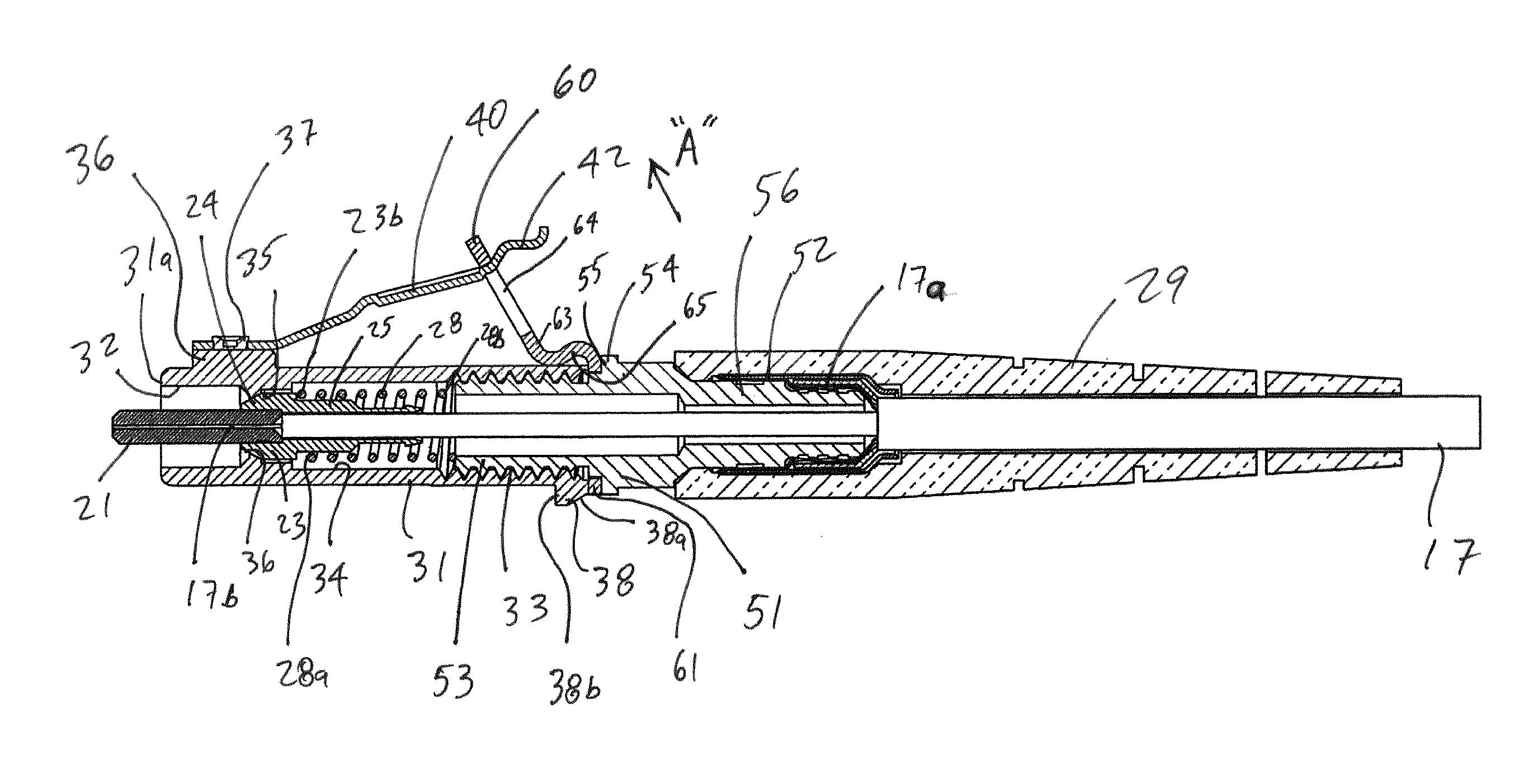
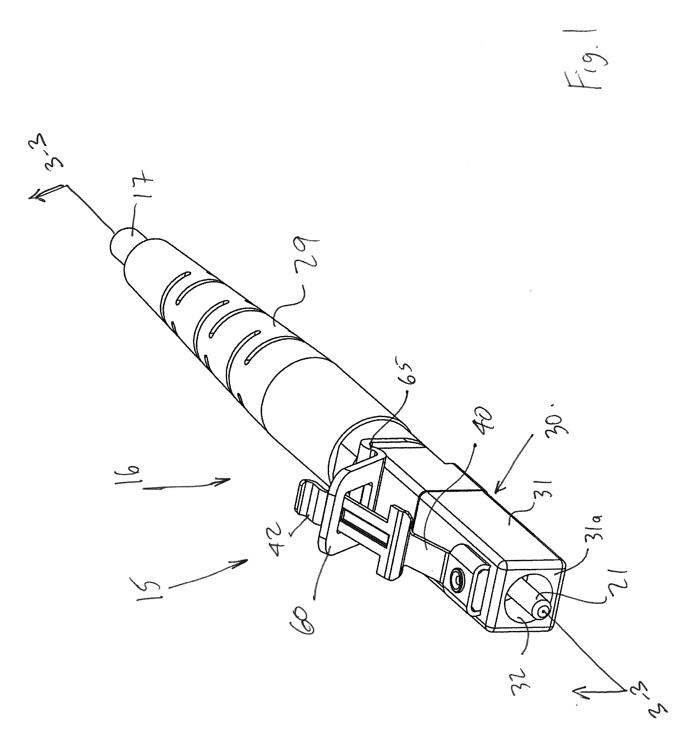
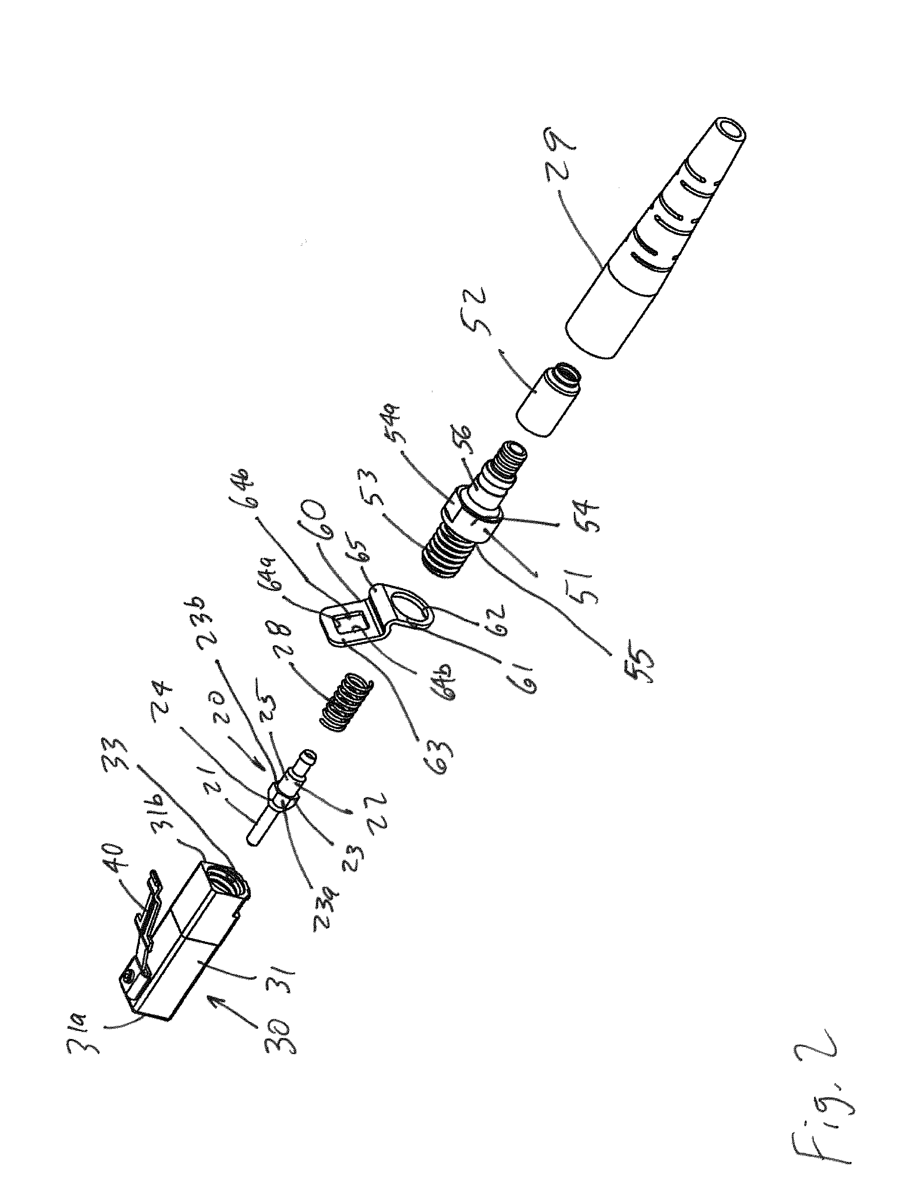
[0013]The metal latch may further include a pair of latching members located between the resilient spaced apart arms and the manually manipulatable portion, with the latching members projecting from the opposite edges of the elongated strip. A latch travel limiting structure may be provided to engage the resilient metal latch and prevent the latch from deflecting beyond a desired predetermined path. The latch travel limiting structure may be configured to prevent the latch from deflecting away from the metal housing more than a predetermined distance and prevent the latch from deflecting out of a common plane that extends through a longitudinal axis of the connector and a longitudinal axis of the metal latch. The latch travel limiting structure may be a metal component having a hole with a portion of the metal latch extending through the hole.

Problems solved by technology

This is a particularly challenging task because the light-carrying region or core of an optical fiber is quite small.
However, such metal housings create challenges relative to the latching structure between components containing the ferrules due to the high precision required and the relatively small distances the ferrules move when mated.
That is, metal latch design and construction are challenging in several aspects.
First, unlike the plastic housing-latch construction, the metal latch is typically a separate part that must be mounted to housing.
Second, a metal latch has its own bending characteristics, which tends to be less stable than that of a plastic latch.

Method used


Image

  • Optical fiber connector
  • Optical fiber connector
  • Optical fiber connector

Examples


Embodiment Construction

[0032]While the Present Disclosure may be susceptible to embodiment in different forms, there is shown in the Figures, and will be described herein in detail, specific embodiments, with the understanding that the disclosure is to be considered an exemplification of the principles of the Present Disclosure, and is not intended to limit the Present Disclosure to that as illustrated.

[0033]As such, references to a feature or aspect are intended to describe a feature or aspect of an example of the Present Disclosure, not to imply that every embodiment thereof must have the described feature or aspect. Furthermore, it should be noted that the description illustrates a number of features. While certain features have been combined together to illustrate potential system designs, those features may also be used in other combinations not expressly disclosed. Thus, the depicted combinations are not intended to be limiting, unless otherwise noted.

[0034]In the embodiments illustrated in the Figu...


PUM


Abstract

An optical fiber connector includes a housing with at least one elongated cylindrical cavity, a fiber holder within the cavity including a ferrule which secures an optical fiber therein and a biasing member engaging the fiber holder to bias the ferrule towards an unmated position. A resilient metal latch is mounted on the housing for releasably securing the optical fiber connector to another component. A latch travel limiting structure prevents the latch from deflecting outside a desired predetermined path. Improved structures for mounting the latch on the housing and for creating a duplex connector assembly are also provided.

Description

REFERENCE TO RELATED APPLICATIONS[0001]The Present Disclosure is a U.S. National Phase Application of PCT Patent Application No. PCT / US2010 / 0046365, entitled “Optical Fiber Connector,” and filed 23 Aug. 2010 with the U.S. Patent and Trademark Office (USPTO). The Present Disclosure claims priority to U.S. Provisional Application No. 61 / 235,914, entitled “Optical Fiber Connector,” and filed 21 Aug. 2009 also with the USPTO. The contents of each of the aforementioned Applications are fully incorporated in their entireties herein.BACKGROUND OF THE PRESENT DISCLOSURE[0002]The Present Disclosure generally relates to optical fiber connectors and, more particularly, to connectors with improved latching structure and duplex clip.[0003]Optical fiber connectors are an essential part of substantially any optical fiber based communication system. For instance, such connectors may be used to join segments of fiber into longer lengths, to connect fiber to active devices such as transceivers, detec...

Claims


Application Information

Patent Timeline
Patent Type & Authority Applications(United States)
IPC IPC(8): G02B6/38
CPCG02B6/381G02B6/3807G02B6/3893G02B6/387G02B6/3809G02B6/3616G02B6/3879
Inventor CHEN, WENZONGERNST, SCOTKUPRIN, IGORSMITH, BRIANSZEWCZYK, JOANNAMATUSZEWSKI, MARK
Owner MOLEX INC
Why Eureka
Try Eureka