Steam generation apparatus for washing machine

Active Publication Date: 2006-01-19
LG ELECTRONICS INC
View PDF13 Cites 52 Cited by
  • Summary
  • Abstract
  • Description
  • Claims
  • Application Information

AI Technical Summary

Benefits of technology

[0011] Therefore, an object of the present invention is to provide a steam generation apparatus for a washing machine which can reduce an overall size of the washing machine and the amount of was

Problems solved by technology

In addition, since washing water should be filled even in the space

Method used


Image

  • Steam generation apparatus for washing machine
  • Steam generation apparatus for washing machine
  • Steam generation apparatus for washing machine

Examples


first embodiment

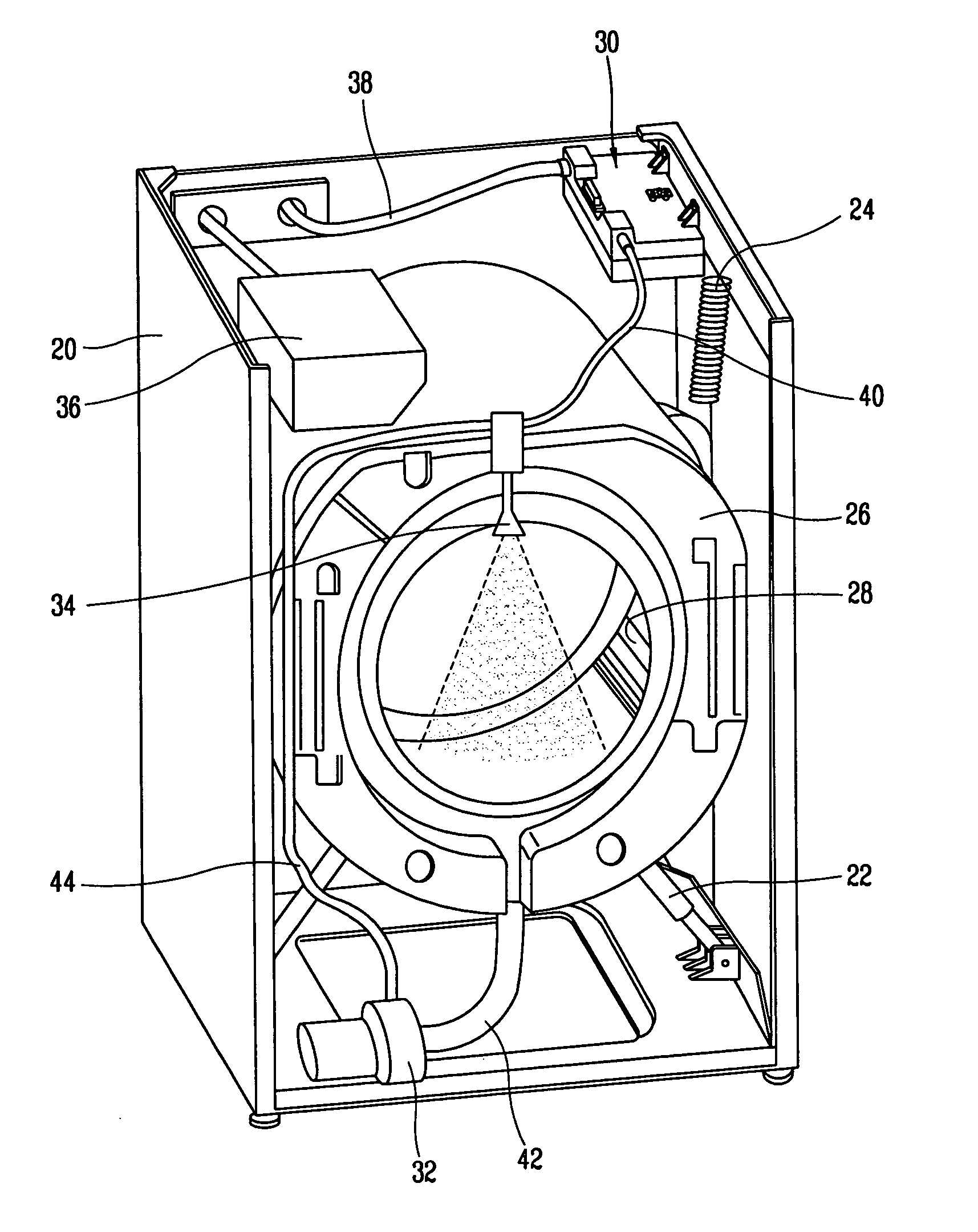
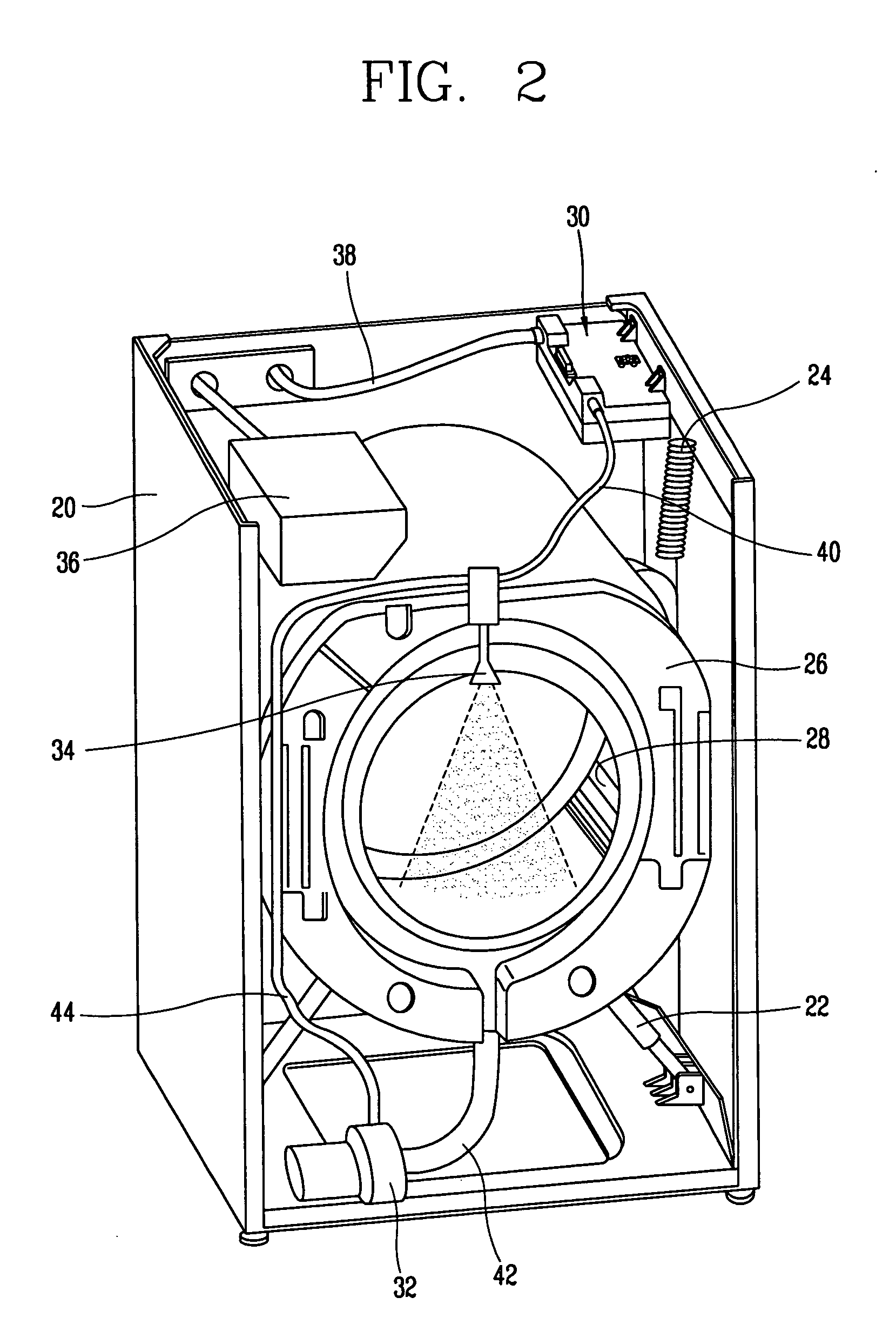
[0037]FIG. 2 is a perspective view of when the front of a washing machine in accordance with the present invention is opened.

[0038] A washing machine in accordance with a first embodiment of the present invention includes: a cabinet 20 forming the exterior thereof; a tub 26 buffered and supported inside the cabinet 20 by a damper 22 and a support spring 24, for storing washing water; a drum 28 rotatably disposed inside the tub 26 to wash and dehydrate laundry; a stream generation apparatus 30 disposed at an upper side of the cabinet 20 to generate steam; a circulation pump 32 disposed under the tub 26 to pump water drained from the tub 26 and re-supply the pumped water into the tub 26; and a spray nozzle 34 for spraying the steam generated from the steam generation apparatus 30 or the water circulated by the circulation pump 32 into the drum 28.

[0039] A detergent box 36 is installed at the upper side of the tub 26, and water required to wash laundry is supplied into the tub 26 toge...

second embodiment

[0056]FIG. 5 is a cross-sectional view of a heater overheating prevention unit in accordance with the present invention.

[0057] A heater overheating prevention unit in accordance with the second embodiment includes a thermo-fuse 70 installed in the heater 52 to cut off the power being supplied to the heater 52 when the heater 52 is overheated above the set temperature.

[0058] The thermo-fuse 70 is installed at one side in the heater 52. when the heater 52 is overheated above the set temperature, the thermo-fuse 70 is out, thereby cutting off the power being supplied to the heater 52.

third embodiment

[0059]FIG. 6 is a cross-sectional view of a steam generation apparatus having a heater overheating prevention unit therein in accordance with the present invention.

[0060] A heater overheating prevention unit in accordance with a third embodiment comprises a thermostat installed at the bottom of the case and disposed in contact with the heater in order to cut off the power being supplied to heater when the temperature of the heater rises above the set temperature.

[0061] The thermostat 72 is disposed in contact with the heater in order to cut off the power being supplied to the heater when the heater is overheated above the set temperature and to prevent overheating of the heater by supplying power to the heater when the temperature of the heater falls.

[0062]FIG. 7 is a perspective view of a steam generation apparatus in accordance with a fourth embodiment of the present invention. FIG. 8 is a plan view from the bottom of the steam generation apparatus in accordance with the fourth ...


PUM


Abstract

A steam generation apparatus for a washing machine includes: a case having an accommodating space for storing water; a heater disposed inside the case to heat the water stored in the case; and a heater overheating prevention unit for cutting off power of the heater when the heater is overheated above the set temperature, so that a fire and deflection of a case can be prevented by preventing overheating of the heater by cutting off power being supplied to the heater when the heater is overheated due to malfunctions of a water level sensor or a clogged spray nozzle or a clogged flow passage.

Description

BACKGROUND OF THE INVENTION [0001] 1. Field of the Invention [0002] The present invention relates to a washing machine, and particularly, to a steam generation apparatus for a washing machine by heating laundry by spraying steam into the laundry. [0003] 2. Description of the Background Art [0004]FIG. 1 is a cross-sectional view of a washing machine in accordance with the conventional art. [0005] A drum washing machine according to the conventional art includes: a cabinet 1 forming the exterior thereof and having an openable door 4 at a front surface thereof; a tub 2 disposed in the cabinet 1 to store washing water; a drum 3 rotatably disposed inside the tub 2 to wash and dehydrate laundry; and a driving motor 7 connected to the drum 3 by a driving shaft 10 to rotate the drum 3. [0006] A damper 6 and a support spring 5 are installed in order to buffer and support the tub 2 inside the cabinet 1. A heater 9 for heating washing water stored in the tub 2 is installed under the tub 2. [00...

Claims


Application Information

Patent Timeline
IPC IPC(8): D06F39/04
CPCD06F33/02D06F2204/04D06F2202/04D06F39/008D06F34/14D06F2103/52D06F2105/28D06F33/47
Inventor KIM, JIN-WOONGWOO, KYUNG-CHULJEON, SI-MOON
Owner LG ELECTRONICS INC
Why Eureka
Try Eureka