Mechanical locking of floor panels

a technology of floor panels and locking mechanisms, which is applied in the direction of walls, building components, constructions, etc., can solve the problems of large gap between the edge portions of the short edges, the inability to use the locking system on the market, and the considerable risk of the short edges being pushed away from each other, so as to reduce the vertical friction of the locking system, prevent the vertical displacement of the adjacent edges, and reduce the vertical friction effect of the locking system

Active Publication Date: 2013-08-13
VÄLINGE INNOVATION AB
View PDF265 Cites 178 Cited by
  • Summary
  • Abstract
  • Description
  • Claims
  • Application Information

AI Technical Summary

Benefits of technology

[0024]The present invention aims at a set of building panels, especially floor panels or a floating flooring with a mechanical locking system on the short edge which is configured to improve installation of floor panel installed with vertical folding and which will counteract or prevent separation of the short edges during installation. The aim of the invention is also to improve installation, strength, quality and production costs of such and similar locking systems. A particular objective is to provide locking systems that could be used to lock thin floorboards, for example with a thickness of 5-10 mm.

Problems solved by technology

Such locking systems are not used on the market.
The inventor has analysed several types of floor panels and discovered that there is a considerable risk that the short edges could be pushed away from each other during installation and that a gap could occur between the edge portions of the short edges.
Such a gap could prevent further installation and the floor panels will not be possible to connect.
It could also cause serious damage to the locking system at the short edges.
Such an installation method is however complicated and difficult to use since three actions have to be combined and used simultaneously in connection with angling down of the long edges.
Most vertical push folding systems, especially such systems that comprise a flexible tongue that bends in the length direction of the joint, are difficult to lock when the first and the last rows are installed.
This leads to the fact that expensive materials or complicated production methods must be used.
This could cause the short edges to separate such that the locking system will be damaged or such that the panels will be difficult to install.
Locking strength, locking quality and production costs are in some of the known vertical locking systems not competitive with traditional mechanical locking systems installed with combinations of angling and horizontal snapping

Method used


Image

  • Mechanical locking of floor panels
  • Mechanical locking of floor panels
  • Mechanical locking of floor panels

Examples


Embodiment Construction

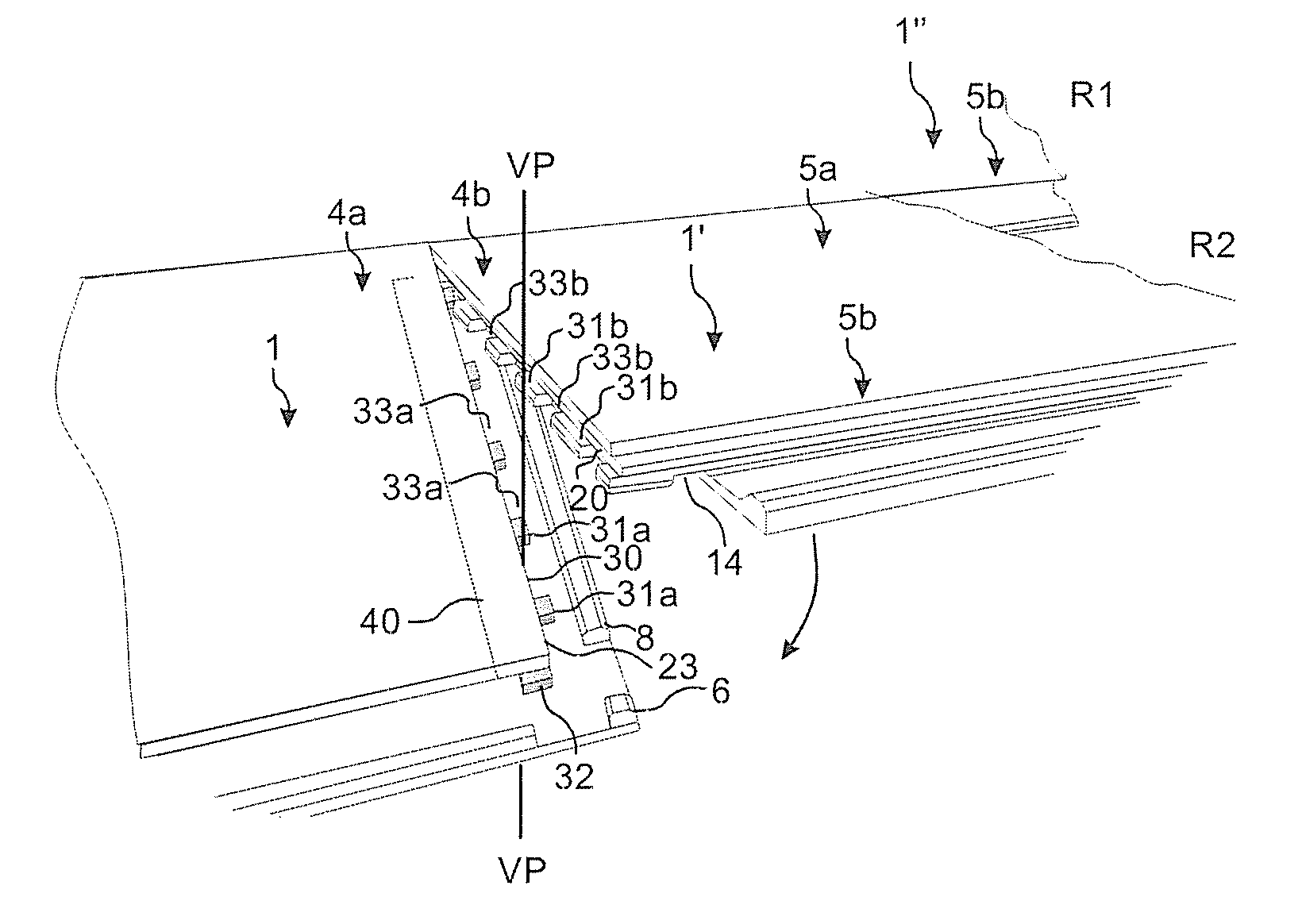
[0133]FIG. 4a shows one embodiment of panels with a vertical push folding locking system according to the invention. The short edges 4a and 4b comprise a displaceable tongue 30 connected to a displacement groove 40 in one edge cooperating with a tongue groove 20 in an adjacent edge for vertical locking of the edges. The displaceable tongue 30 and the tongue groove 20 comprise protrusions 31a, 31b and cavities 33a, 33b. The protrusions 31a on the displaceable tongue extend horizontally beyond the vertical plane VP and the upper part of the edge. The short edges comprise furthermore a locking strip 6 with a locking element 8 in one edge that cooperates with a locking groove in an adjacent edge for horizontal locking of the edges. The panels are installed as follows. A first panel 1″ in a first row R1 is connected to a second 1 panel in a second row R2. A new panel 1′ is moved with its long edge 5a towards the long edge 5b of first panel 1″ at a normal installation angle of about 25-30...


PUM

PropertyMeasurementUnit
widthaaaaaaaaaa
anglesaaaaaaaaaa
thicknessaaaaaaaaaa

Abstract

Floor panels are shown, which are provided with a mechanical locking system having tongue and grooves provided with protrusions and cavities which are displaceable in relation to each other and configured such that the protrusions can obtain a vertically unlocked position where they match the cavities and a vertically locked position where the protrusions overlap each other.

Description

PRIORITY[0001]This application claims the benefit of U.S. Provisional Application No. 61 / 006,780, filed Jan. 31, 2008, and U.S. Provisional Application No. 61 / 050,443, filed May 5, 2008, both of which are expressly incorporated herein.AREA OF INVENTION[0002]The invention generally relates to the field of floor panels with mechanical locking systems comprising a separate displaceable tongue allowing easy installation. The invention provides new improved locking systems and methods to install and disconnect building panels, especially floor panels and methods to produce the locking system.BACKGROUND OF THE INVENTION[0003]In particular, yet not restrictive manner, the invention concerns a mechanical locking system for rectangular floor panels with long and short edges. Such floor panels are generally installed with an angling of long edges. Short edges could be connected with angling, horizontal snapping or insertion along the short edge. The installation requires three actions since a...

Claims


Application Information

Patent Timeline
Patent Type & Authority Patents(United States)
IPC IPC(8): E04B2/00
CPCB27F1/02B27G13/14E04F15/02B27F1/08Y10T408/03E04F2201/0138E04F2201/0146E04F2201/0153E04F2201/0161E04F2201/021E04F2201/028E04F2201/041E04F2201/0511E04F2201/0523E04F2201/0541
Inventor BOO, CHRISTIANSJOSTRAND, MATTIASPALSSON, AGNEHAKANSSON, NICLASPERVAN, DARKO
Owner VÄLINGE INNOVATION AB
Why Eureka
Try Eureka