Portable on vehicle dynamometer

a dynamometer and vehicle technology, applied in the direction of vehicle testing, engine testing, structural/machine measurement, etc., can solve the problems of not being used often and occupying a considerable spa

Active Publication Date: 2013-08-13
DYNOCOM INDS
View PDF8 Cites 27 Cited by
  • Summary
  • Abstract
  • Description
  • Claims
  • Application Information

AI Technical Summary

Benefits of technology

[0003]A portable on vehicle dynamometer (“POD”) is provided for determining power output from a drive shaft. The POD has a rigid frame, a load shaft, and an eddy current brake. The eddy current brake has a stator connected to the rigid frame and a rotor connected to the load shaft. The stator is secured around an exterior of the drive shaft. A hub coupling is secured to a first end of the load shaft and connected to the drive shaft for transferring power to the load shaft. The rigid frame has two outwardly extending support arms and arm locks...

Problems solved by technology

Such configurations take up consid...

Method used


Image

  • Portable on vehicle dynamometer
  • Portable on vehicle dynamometer
  • Portable on vehicle dynamometer

Examples


Embodiment Construction

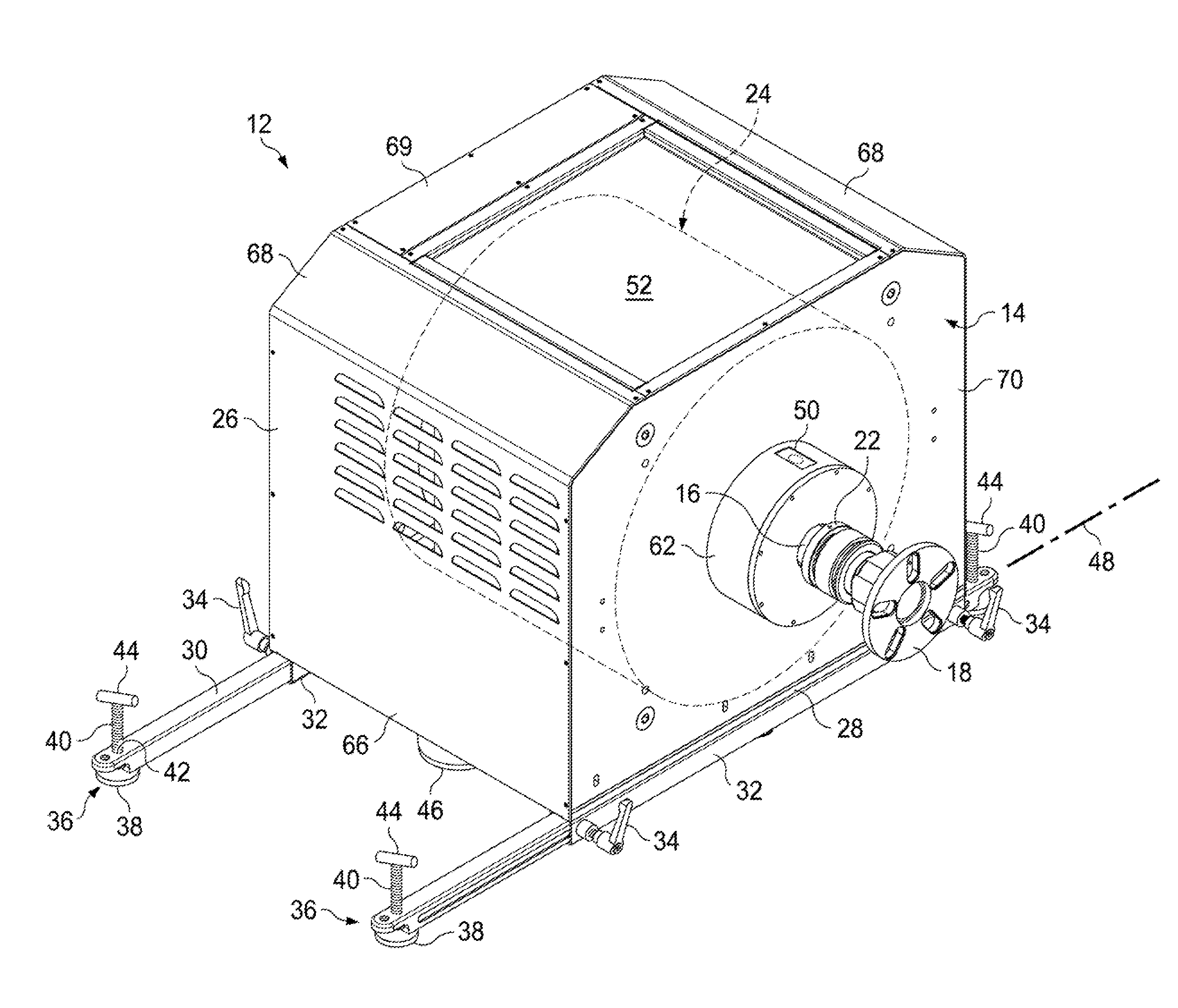
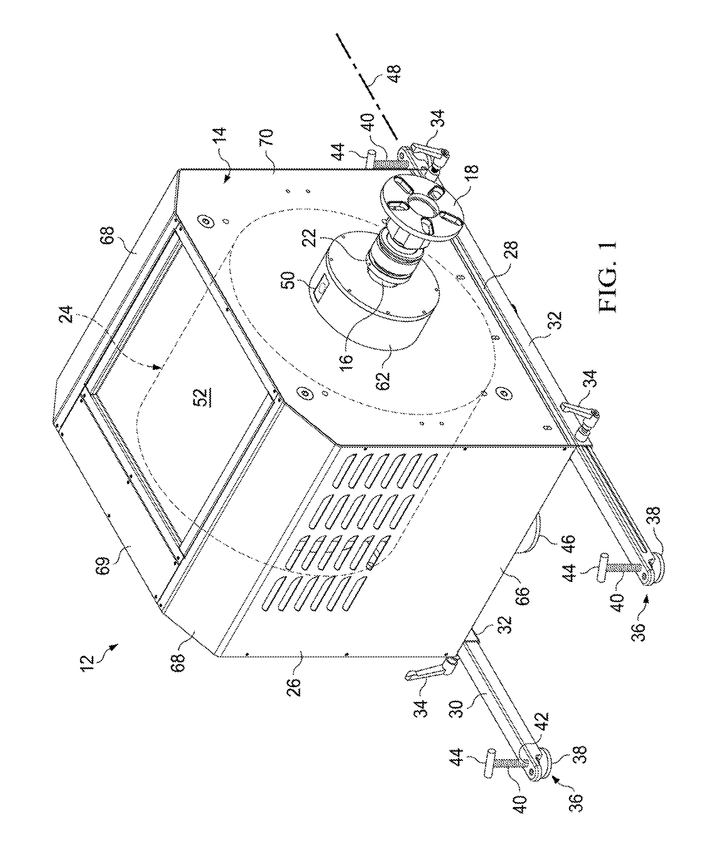
[0018]FIGS. 1 and 2 are perspective views of a portable on-vehicle dynamometer (“POD”) 12 for coupling directly to an axle of the vehicle to measure the power output of the axle. The POD 12 has a housing 14 from which extends a load shaft 16. The load shaft 16 is secured with a hub coupling 18, a universal joint 20, and a quick connect 22 to an eddy current brake 24. The eddy current brake 24 preferably is of the type having a stator 56 and a rotor drum 54, but in some embodiments other types of eddy current brakes may be used, such as the eddy current brake 134 shown in FIG. 11. A hub of a wheel of a vehicle may be connected directly to the hub coupling 18 for connecting the vehicle directly to the POD 12 to determine the power output of the vehicle, without requiring jack stands and the like to support the vehicle over a conventional type dynamometer.

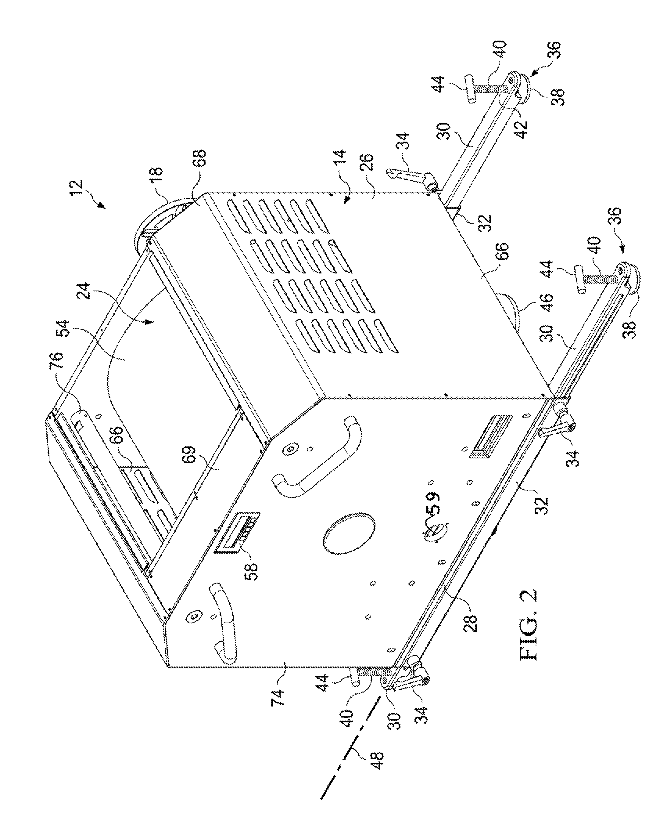
[0019]FIG. 3 is a perspective view of the POD 12 with two cover panels 66 and 68 removed. The housing 14 defines an enclosure 26 hav...


PUM


Abstract

A portable on vehicle dynamometer (12) has a rigid frame (64), a load shaft (16), and an eddy current brake (24) with a stator (56) connected to the rigid frame (64) and a rotor (54) connected to the load shaft (16). A hub coupling (18) is secured to a first end of the load shaft (16) and connected to the drive shaft. The rigid frame (64) has two outwardly extending support arms (30) for securing in outwardly extending, fixed positions. Two roller assemblies (46) are mounted to a lower end of the rigid frame (64) for multidirectional movement of the dynamometer (12). Preferably the eddy current brake (24) comprises a cylindrically-shaped rotor drum (54) extending exteriorly around the stator (56), and the stator (56) comprises a plurality of stator coils (94) extending exteriorly around the load shaft (16), spaced apart from an interior of the rotor drum (54).

Description

TECHNICAL FIELD OF THE INVENTION[0001]The present invention relates in general to dynamometers, and in particular to a dynamometer for coupling directly an output shaft for measuring power transmitted by the output shaft.BACKGROUND OF THE INVENTION[0002]Prior art dynamometers have been provided for measuring the power output from drive shafts, such as those for motor vehicles. Typical automotive chassis type dynamometers have rotary drums on top of which the wheels of vehicles are placed. Power is then transferred from an engine, to a drive shaft, to the wheels of the vehicle and then to the rotary drum of the chassis dynamometer. This type of dynamometer requires that the dynamometer either be buried in a garage floor, or that a rack is provided to suspend a vehicle above the dynamometer. Such configurations take up considerable space, and may not be often used. Considerable garage space is also used when hydraulic dynamometers are used, due to the ancillary hydraulic equipment req...

Claims


Application Information

Patent Timeline
IPC IPC(8): G01M17/007
CPCG01L3/24
Inventor ARSENEAU, PAUL N.
Owner DYNOCOM INDS
Why Eureka
Try Eureka