Surgical rod scorer and method of use of the same

a surgical rod and scorer technology, applied in the field of surgical rod scorers, can solve the problem of not providing a clean cut of the surgical rod

Active Publication Date: 2013-08-13
K2M
View PDF110 Cites 10 Cited by
  • Summary
  • Abstract
  • Description
  • Claims
  • Application Information

AI Technical Summary

Problems solved by technology

However, this type of rod cutter applies a large amount of force to the surgical rod, which, in turn, effectively shears the surgical rod apart; this type of rod cutter does not provide a clean cut of the surgical rod.

Method used


Image

  • Surgical rod scorer and method of use of the same
  • Surgical rod scorer and method of use of the same
  • Surgical rod scorer and method of use of the same

Examples


Embodiment Construction

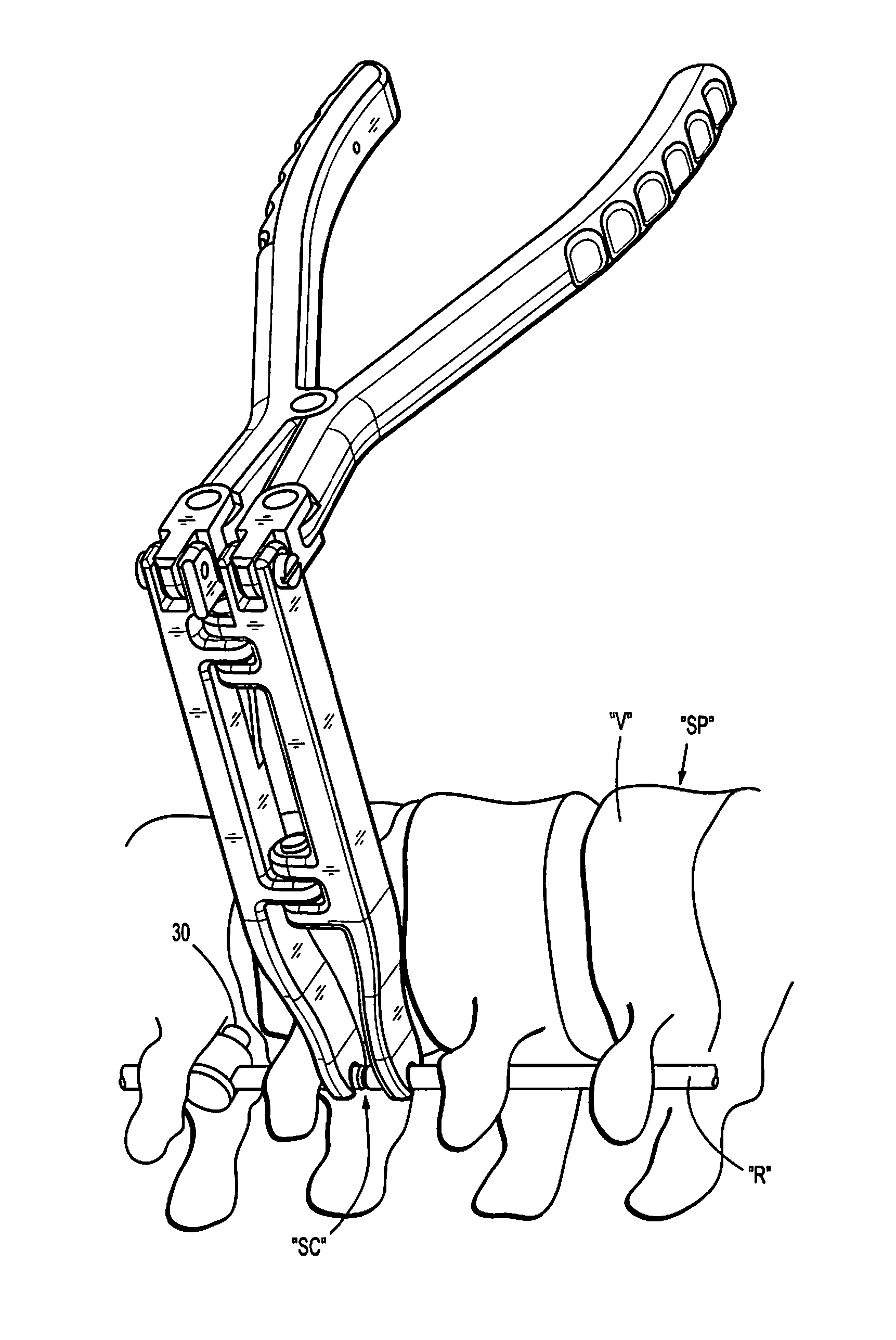
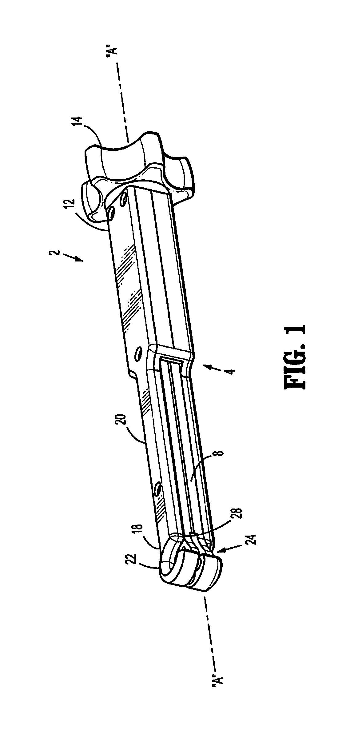
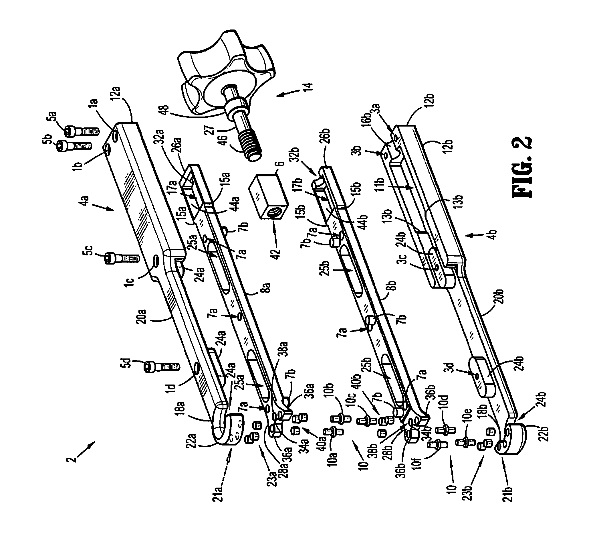
[0025]In the following description, as is traditional, the term “proximal” refers to a portion of a surgical instrument closer to the operator while the term “distal” refers to a portion of a surgical instrument farther from the operator. In addition, the term “cephalad” is used in this application to indicate a direction toward a patient's head, whereas the term “caudad” indicates a direction toward the patient's feet. Further still, for the purposes of this application, the term “medial” indicates a direction toward the middle of the body of the patient, whilst the term “lateral” indicates a direction toward a side of the body of the patient (i.e., away from the middle of the body of the patient). The term “posterior” indicates a direction toward the patient's back, and the term “anterior” indicates a direction toward the patient's front. In the following description, well-known functions or constructions are not described in detail to avoid obscuring the present disclosure in unn...


PUM

PropertyMeasurementUnit
score depthaaaaaaaaaa
diameteraaaaaaaaaa
bendingaaaaaaaaaa

Abstract

A method for cutting surgical rod in situ is provided. The method includes positioning an operable end of a surgical rod scorer around surgical rod that has been previously affixed to a spinal segment via at least two pedicle screws. A portion of the surgical rod is scored with the surgical rod scorer. The scored surgical rod is grasped with a surgical rod bender. And, the scored surgical rod is bent such that the surgical rod separates along the scored portion of the surgical rod.

Description

CROSS-REFERENCE TO RELATED APPLICATIONS[0001]The present application is a continuation-in-part of pending U.S. patent application Ser. No. 12 / 904,817 to McClintock et al., filed on Oct. 14, 2010, which claims the benefit of and priority to U.S. Provisional Application No. 61 / 278,924 to McClintock et al., filed on Oct. 14, 2009, the entire contents of each of these applications is incorporated by reference herein.BACKGROUND[0002]1. Technical Field[0003]The present disclosure relates to a surgical rod scorer and method of use of the same. More particularly, the present disclosure relates to a surgical rod scorer including a plurality of cutting elements aligned along a common scoring axis of the surgical rod scorer.[0004]2. Description of Related Art[0005]Disease, the effects of aging, or physical trauma resulting in damage to the spine has been treated in many instances by fixation or stabilization of the affected vertebra. A wide variety of spinal fixation apparatuses have been empl...

Claims


Application Information

Patent Timeline
Patent Type & Authority Patents(United States)
IPC IPC(8): A61B17/70
CPCA61B17/8863B23D31/002B26D3/08B26F3/002B26B25/005Y10T225/321Y10T225/12
Inventor MCCLINTOCK, LARRYSTRAUSS, KEVIN RSANDHU, FAHEEM
Owner K2M
Why Eureka
Try Eureka