
Self-guide long-arm solid percutaneous pedicle screw
A pedicle screw and self-guided technology, applied in the field of pedicle screw, can solve the problems of insufficient biomechanical strength, complicated manufacturing process and high price, and achieve the advantages of preventing truncation or bending deformation, high mechanical strength and strong support. Effect
- Summary
- Abstract
- Description
- Claims
- Application Information
AI Technical Summary
Problems solved by technology
Method used
Image

Examples
Embodiment Construction
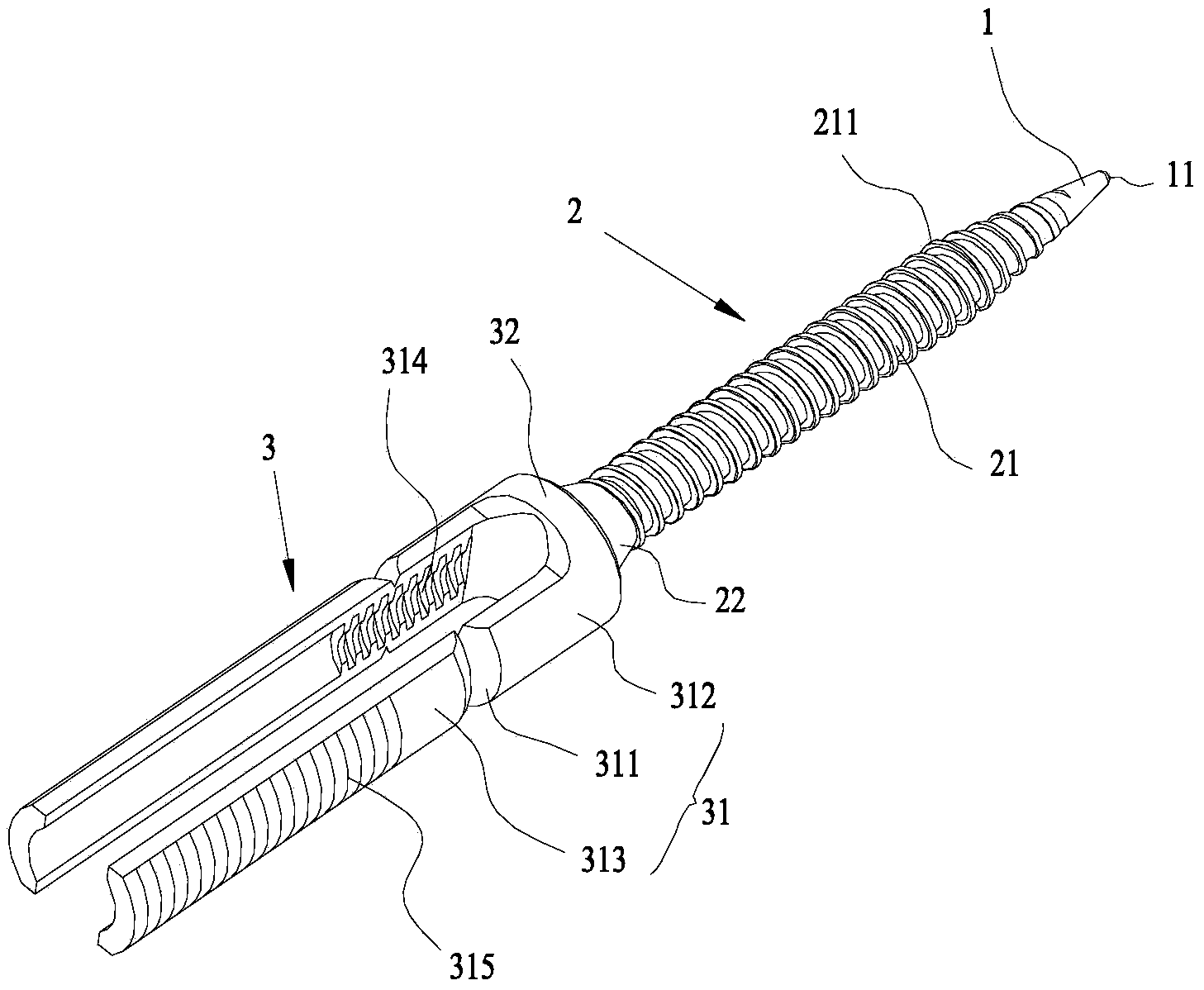
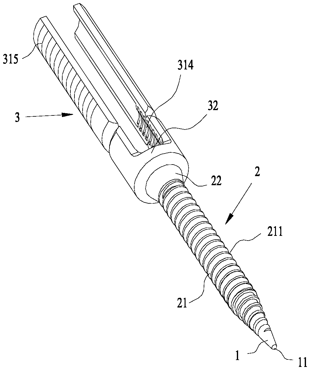
[0024] like Figure 1~2 The shown self-guiding long-arm solid percutaneous pedicle screw includes a screw head 1, a screw body 2, and a screw tail 3 connected sequentially from front to back. The screw head 1 is a solid cone, and the cross-sectional size of the screw head 1 is Gradually increase from front to back; nail body 2 includes a solid cylindrical front section 21 and a solid conical rear section 22, the front end of the cylindrical front section 21 and the rear end of the nail head 1 smoothly transition, the rear end of the cylindrical front section 21 and the The front end of the cone rear section 22 smoothly transitions, and the outer peripheral wall of the cylinder front section 21 is provided with an external thread 211; the nail tail 3 is U-shaped, has two fixed arms 31 and a nail seat 32 connecting the two fixed arms 31; the cone rear section The rear end of 22 links to each other with nail seat 32, and the section of this cone rear section 22 gradually increase...
PUM
| Property | Measurement | Unit |
|---|---|---|
| Length | aaaaa | aaaaa |
| Length | aaaaa | aaaaa |
| Length | aaaaa | aaaaa |
Abstract
Description
Claims
Application Information