
Aligned single-walled carbon nanotube aggregate, bulk aligned single-walled carbon nanotube aggregate, powdered aligned single-walled carbon nanotube aggregate, and production method thereof

Inactive Publication Date: 2010-03-11
NAT INST OF ADVANCED IND SCI & TECH
View PDF2 Cites 56 Cited by
  • Summary
  • Abstract
  • Description
  • Claims
  • Application Information

AI Technical Summary

Benefits of technology

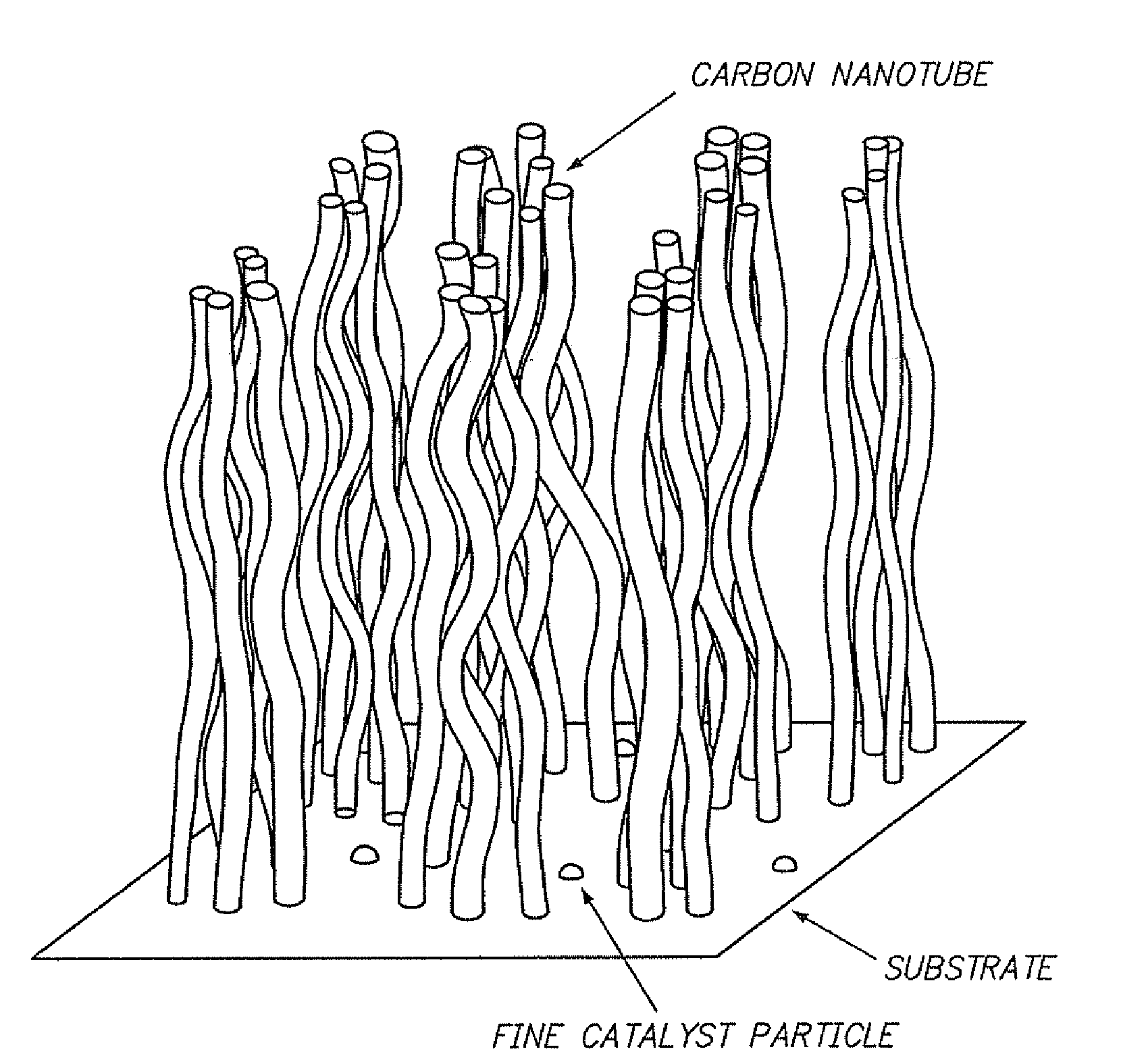
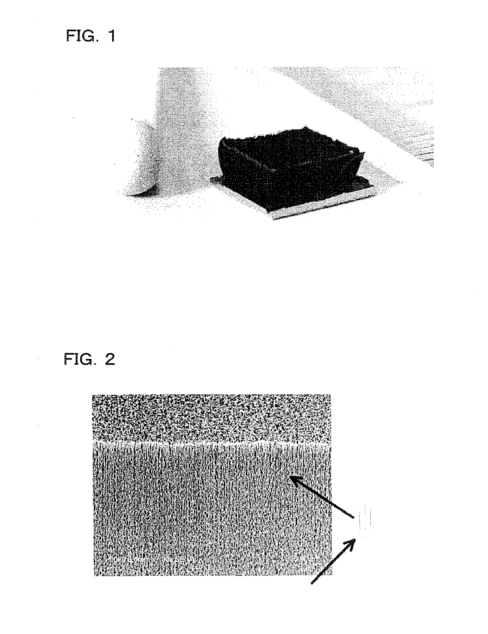
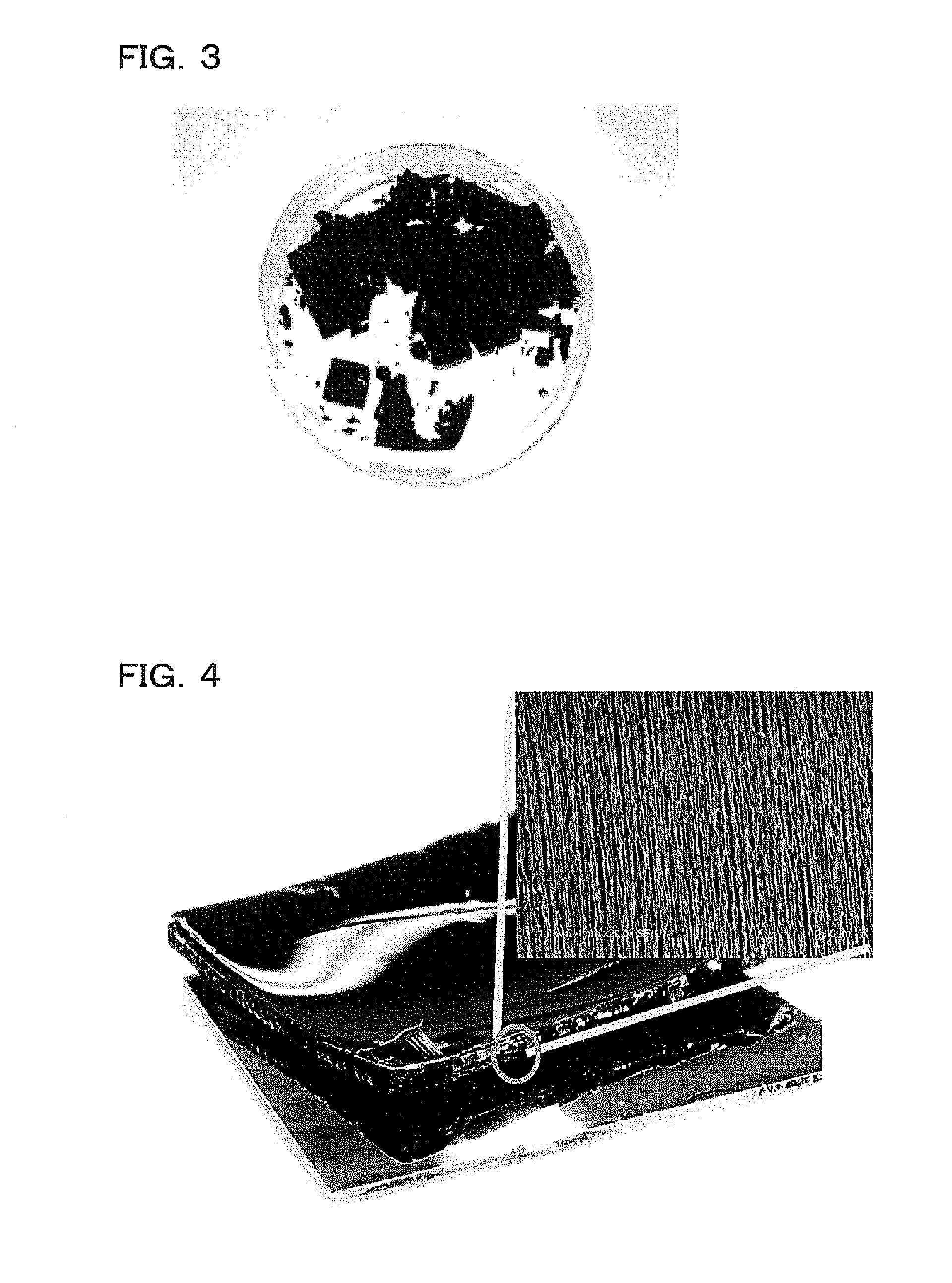
[0007]In view of the problems in the prior art described above, the present invention mainly intends to provide an aligned single-walled CNT aggregate, a bulk aligned single-walled CNT aggregate, and an powdered aligned single-walled CNT aggregate which can be produced easily and has a high specific surface area, in which individual CNTs are aligned and which has excellent shape processability due to low bulk density (low weight per unit volume), and to provide a production method for the same. “Aligned single-walled CNT aggregate” referred to in the present specification means a aggregate of a plurality of single-walled CNTs grown to a predetermined direction from a substrate used for growth, “bulk aligned single-walled CNT aggregate” means an object obtained by peeling the aligned single-walled CNT aggregates together from a substrate, and “powdered aligned single-walled CNT aggregate” means an object obtained by peeling the aligned single-walled CNT aggregates from the substrate into a powder form.
[0024]The present invention can provide an aligned single-walled CNT aggregate, a bulk aligned single-walled CNT aggregate, and a powdered aligned single-walled CNT aggregate having an extremely useful properties such as high specific surface area, high alignment property, and low density. CNT is a material having a one-dimensional structure with an extremely high aspect ratio and the function thereof also shows a anisotropy. Accordingly, when individual CNTs constituting a CNT aggregate are aligned, the properties of each CNTs are directionally anisotropic, as a result, a CNT structure of superior properties can be obtained. That is, the aligned single-walled CNT aggregate of the invention in which each of CNTs is aligned shows higher anisotropy in view of the transmission property in the alignment direction compared with a CNT aggregate in which the directions of individual CNTs are not-ordered, that is, with no alignment. Due to the high anisotropy, the CNT aggregate shows more preferred electric property (for example, higher conductivity), more preferred mechanical property (for example, higher strength), and more preferred thermal property (for example, higher heat conductivity). Further, the property of such CNT aggregate is different between the alignment direction and other directions, that is, it is anisotropic, and thus is effective, for example, to selectively diffuse and discharge heat or the like in a desired direction and this is suitable for applications such as a heat conductive material.
[0027]In addition, the aligned single-walled CNT aggregate of the invention which is properly aligned and at a low density is easy for the density control by a post treatment process after growth and CNTs can be packed at a high density with no gaps like a flattened field of corn by way of a density-increasing process. In this case, the aligned single-walled CNT aggregate can be molded into various shapes by controlling the density-increasing process.

Problems solved by technology

However, since CNT is an elongate flexible material having an extremely high aspect ratio and also a material having high tendency to stick together by the strong Van der Waals force, it tends to form an aggregate which is not ordered and not aligned and has a small specific surface area.
Then, it is extremely difficult to deconstruct the aggregate once it was in a non-ordered and non-aligned state.
Accordingly, it is extremely difficult to produce an aligned CNT aggregate having high specific surface area, alignment property, and excellent processability to various forms and shapes by existent techniques.

Method used


Image

  • Aligned single-walled carbon nanotube aggregate, bulk aligned single-walled carbon nanotube aggregate, powdered aligned single-walled carbon nanotube aggregate, and production method thereof
  • Aligned single-walled carbon nanotube aggregate, bulk aligned single-walled carbon nanotube aggregate, powdered aligned single-walled carbon nanotube aggregate, and production method thereof
  • Aligned single-walled carbon nanotube aggregate, bulk aligned single-walled carbon nanotube aggregate, powdered aligned single-walled carbon nanotube aggregate, and production method thereof

Examples


example 1

Production by Substrate 1

[0219]An aligned single-walled CNT aggregate according to the invention will be described in details with reference to specific examples. The property of the aligned single-walled CNT aggregate produced by this example depends on production conditions. In the production conditions of Example 1 to be described below, typical values are 0.03 g / cm3 for the density, 1200 m2 / g for the BET-specific surface area, 10 for G / D, 2.5 nm for the average outer diameter, 2 nm for the full-width at half maximum, 99.9% for the carbon purity, and 0.8 for the Hermann's orientation factor.

[0220]The production step according to this example includes, as shown in the flow chart of FIG. 37, a preparation step for a catalyst substrate and a synthesis step for a single-walled CNT. The preparation step for the catalyst substrate includes a step of forming a co-catalyst layer of 40 nm thickness comprising alumina (Al2O3) on a silicon substrate by RF sputtering and forming a catalyst l...

example 2

Production by Substrate 2

[0228]Another method of producing an aligned single-walled CNT aggregate according to the invention (Example 2) is to be described below. FIG. 40 shows a flow chart for the production step according to this example and detailed process conditions are shown in FIG. 41.

[0229]A silicon substrate 32 vapor deposited with the same catalyst metal (Al2O3+Fe) as in Example 1 is provided and the substrate 32 is transported and installed in the synthesis furnace 33 of the CVD apparatus 31 kept at a room temperature for the furnace room temperature and at of 1.02×10⁵ Pa for the furnace pressure (substrate transporting step S21), at 600 sccm of He (atmospheric gas) and 400 sccm of H2 (reducing gas) are introduced into the furnace and the furnace temperature is elevated at a temperature elevation rate of 50° C. / min for 15 min (formation step S2). That is, a significant difference between this example and Example 1 described above is elevation of temperature in the furnace...

example 3

Production by Granular or Linear Base Material

[0237]The aligned single-walled CNT aggregate according to the invention is to be described by way of a production process in a case of using a granular shaped base material or a linear shaped base material as a base material.

[0238]While the production method according to this example is identical with that in Example 1, a spherical granular shaped base material or a linear shaped base material of SUS 304 in a metal mesh form is used as the base material instead of the silicon substrate in Example 1.

[0239]FIG. 55 shows a digital photograph of aligned single-walled CNT aggregates grown on alumina particles having an average diameter of 3 mm. It can be seen that the aligned single-walled CNT aggregate having a height of several hundred μm can be produced on the alumina particle. Further, FIG. 56 shows a digital photograph of aligned single-walled CNT aggregate grown on silica particles having an average diameter of 300 μm.

[0240]Then, FIG. ...


PUM

PropertyMeasurementUnit
Pressureaaaaaaaaaa
Diameteraaaaaaaaaa
Diameteraaaaaaaaaa

Abstract

This invention intends to provide an aligned single-walled CNT aggregate and the like which can be produced easily and has a high specific surface area, in which individual CNTs are aligned and which has excellent shape processability due to low bulk density. The aligned single-walled CNT aggregate of this invention comprises a base material, catalyst particles with a density of 1×10¹⁰ to 5×10¹³N / cm2 disposed on the base material, and a plurality of single-walled carbon nanotubes (CNTs) grown from the fine particles of the catalyst, in which the plurality of single-walled CNTs have a specific surface area of 600 m2 / g to 2600 m2 / g, and a weight density from 0.002 g / cm3 to 0.2 g / cm3, and the alignment degree is defined by a specific condition or conditions.

Description

TECHNICAL FIELD[0001]The present invention relates to an aligned single-walled carbon nanotube aggregate including a bulk aligned single-walled carbon nanotube aggregate and a powdered aligned single-walled carbon nanotube aggregate, and more specifically, it relates to an aligned single-walled carbon nanotube aggregate, a bulk aligned single-walled carbon nanotube aggregate, a powdered aligned single-walled carbon nanotube aggregate having excellent shape processability and realizing high purity, high specific surface area, large scaling and patterning, an aspect of which has not been hitherto been achieved, and a production method thereof.BACKGROUND ART[0002]In recent years, development of carbon nanotubes (CNTs) has been expected for new functional materials such as new electronic device materials, optical device materials, conductive materials, and bio-related materials, and studies have been progressed earnestly for application use, quality, mass productivity, etc.[0003]Among C...

Claims


Application Information

Patent Timeline
IPC IPC(8): B32B5/02B05D5/00
CPCB82Y30/00B82Y40/00C01B31/0233C01B2202/02C01B2202/08C01B2202/20Y10T428/24802C01B2202/32C30B11/12C30B25/00C30B29/602C30B29/605C01B2202/30C01B32/162
Inventor HATA, KENJIFUTABA, DON N.YUMURA, MOTOO
Owner NAT INST OF ADVANCED IND SCI & TECH
Learn More