Isolated thermal interface

a thermal interface and isolation technology, applied in the direction of chemistry apparatus and processes, synthetic resin layered products, coatings, etc., can solve the problems of system failure, affecting the performance of the overall system, and affecting the performance of the individual components

Inactive Publication Date: 2007-01-23
NEOGRAF SOLUTIONS LLC
View PDF21 Cites 53 Cited by
  • Summary
  • Abstract
  • Description
  • Claims
  • Application Information

AI Technical Summary

Benefits of technology

[0007]An object of the present invention is to provide a thermal interface material that does not exhibit flaking from the edges or major surfaces of the thermal interface material.

Problems solved by technology

However, microprocessors, integrated circuits and other sophisticated electronic components typically operate efficiently only under a certain range of threshold temperatures.
The excessive heat generated during operation of these components can not only harm their own performance, but can also degrade the performance and reliability of the overall system and can even cause system failure.
The increasingly wide range of environmental conditions, including temperature extremes, in which electronic systems are expected to operate, exacerbates these negative effects.
However, there is a concern in the electronics industries to which the use of a graphite-based thermal interface is directed that graphite particles can flake off, and the flakes can mechanically (ie., in the same manner as dust particles) and, due to the conductive nature of graphite, electrically interfere with operation of the component and device in which the thermal interface is employed.
One drawback to this approach, however, is in the labor-intensive method of manufacture.
Also, leaving the top (as opposed to the edges) of the graphite thermal interface uncovered does not fully address the flaking issues that are of concern, and does not address at all the perception that electrical interference is an issue.

Method used


Image

  • Isolated thermal interface
  • Isolated thermal interface
  • Isolated thermal interface

Examples


Embodiment Construction

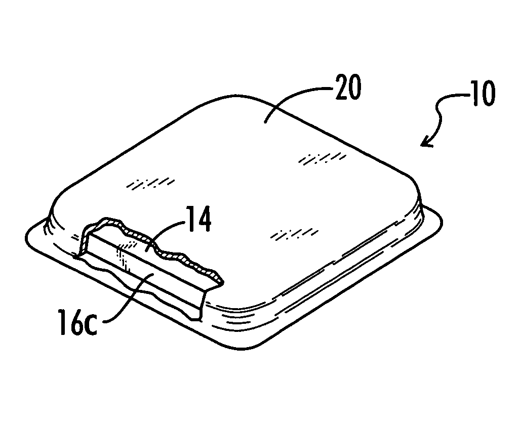
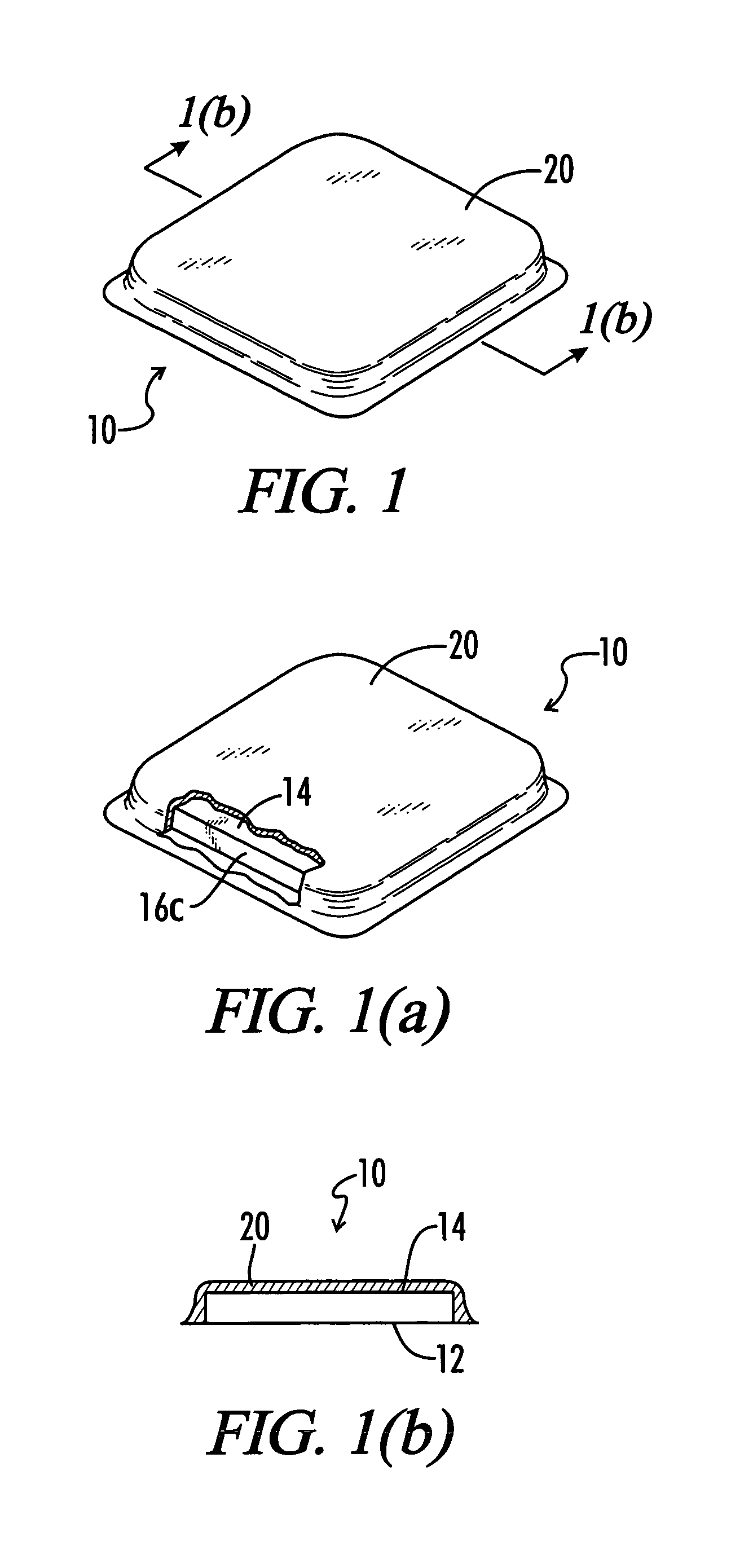
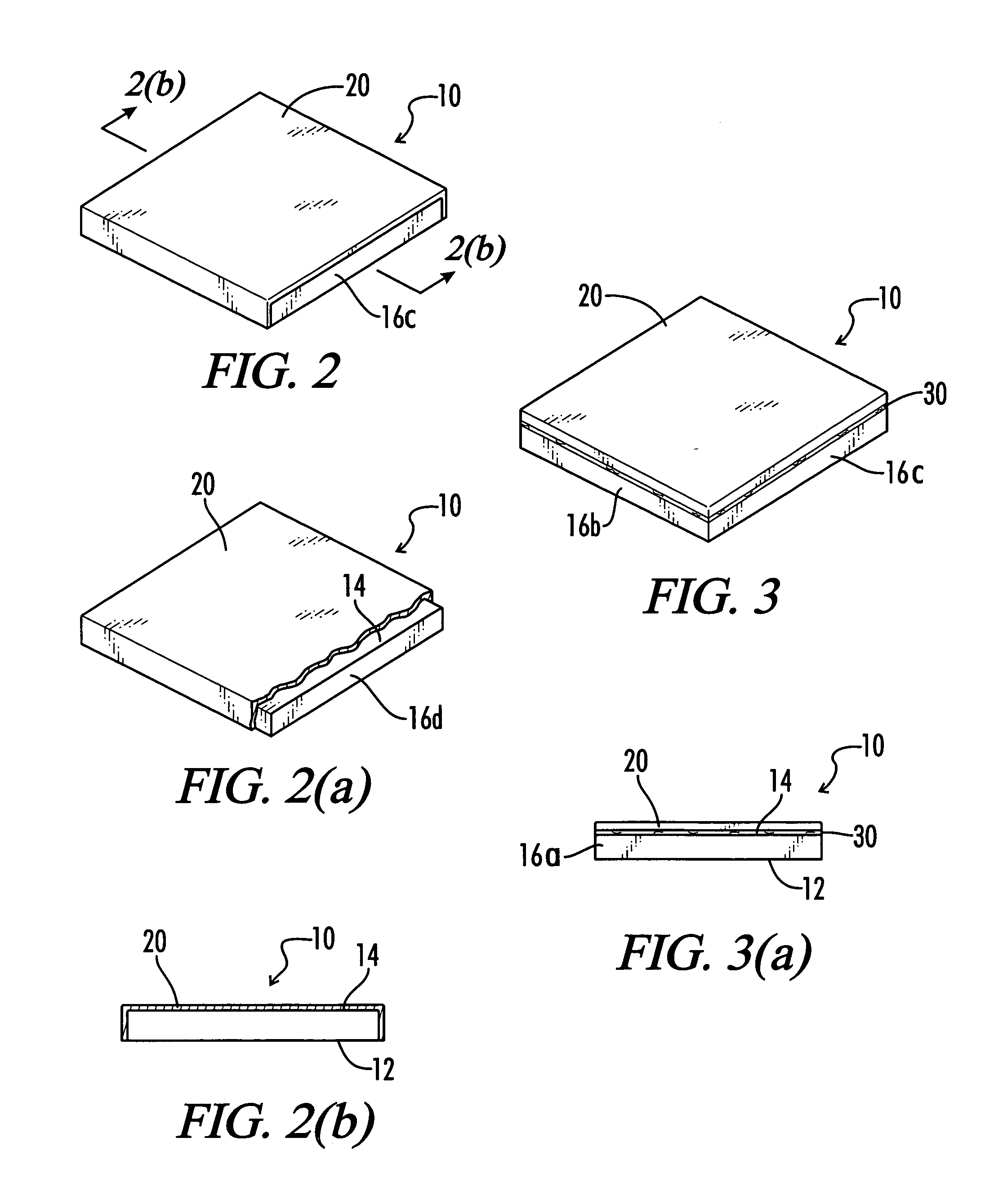
[0025]Referring to the drawings in detail, a thermal interface prepared in accordance with the present invention is shown and generally designated by the reference numeral 10. It should be noted that for the sake of clarity not all the components and elements of interface 10 may be shown and / or marked in all the drawings. Also, as used in this description, the terms “up,”“down,”“top,”“bottom,” etc. refer to thermal interface 10 when in the orientation shown in FIG. 1(a). However, the skilled artisan will understand that thermal interface 10 can adopt any particular orientation when in use.

[0026]Thermal interface 10 is intended to be used to facilitate the dissipation of heat from a heat source, more particularly from an electronic component (not shown). The electronic component can comprise any electronic device or component that produces sufficient heat to interfere with the operation of the electronic component or the system of which the electronic component is an element, if not ...


PUM

PropertyMeasurementUnit
thicknessaaaaaaaaaa
thicknessaaaaaaaaaa
densityaaaaaaaaaa

Abstract

An isolated thermal interface is presented. The inventive interface includes a flexible graphite sheet having two major surfaces, at least one of the major surfaces coated with a protective coating sufficient to inhibit flaking of the particles of graphite.

Description

TECHNICAL FIELD[0001]The invention relates to an isolated thermal interface for electronic devices, comprising an article formed of a flexible graphite sheet that is sealed to inhibit mechanical and electrical interference potentially caused by the graphite.BACKGROUND OF THE INVENTION[0002]With the development of more and more sophisticated electronic components, relatively extreme temperatures can be generated. This is clearly true with respect to electronic components capable of increasing processing speeds and higher frequencies, having smaller size and more complicated power requirements, and exhibiting other technological advances. These components include microprocessors and integrated circuits in electronic and electrical components and systems as well as in other devices such as high power optical devices. However, microprocessors, integrated circuits and other sophisticated electronic components typically operate efficiently only under a certain range of threshold temperatu...

Claims


Application Information

Patent Timeline
Patent Type & Authority Patents(United States)
IPC IPC(8): H01L23/34B32B27/06C09D5/00H01L23/373
CPCB32B27/06C09D5/00H01L23/373H01L23/3735H01L2924/0002H01L2924/00
Inventor TZENG, JING-WENKRASSOWSKI, DANIEL WITOLD
Owner NEOGRAF SOLUTIONS LLC
Why Eureka
Try Eureka