Wearable remote control with a single control button

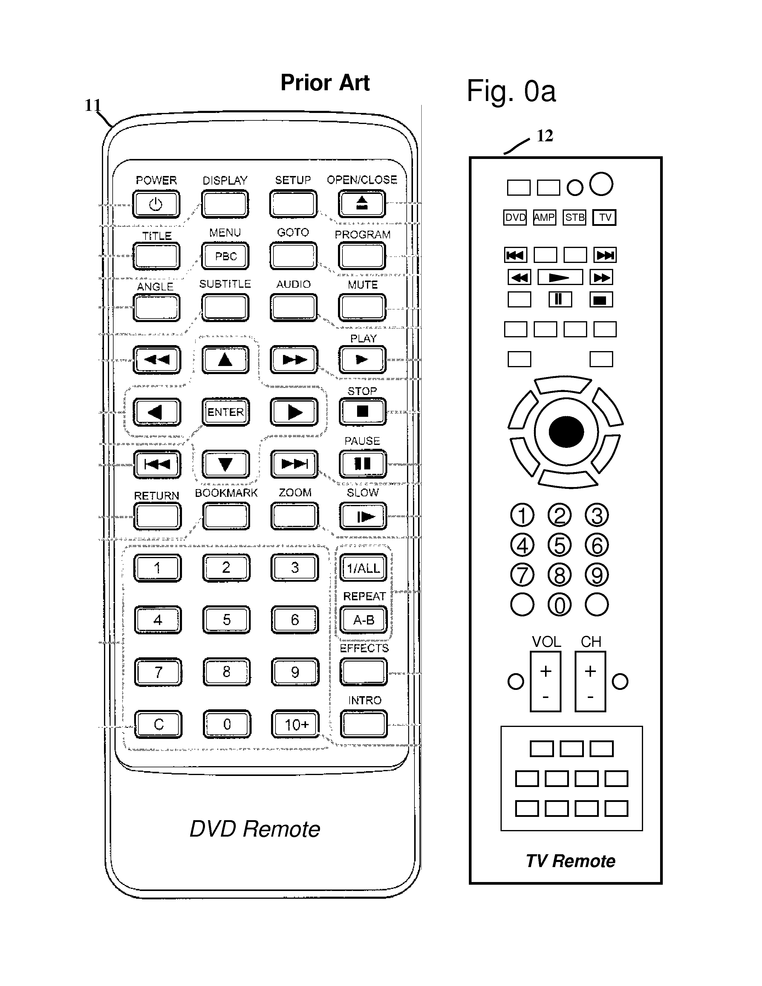
a remote control and control button technology, applied in the field of remote control and/or interaction with electronic devices, can solve the problems of increasing user complexity, complex current remote control use, and many users not knowing what all the buttons do or how to us

Inactive Publication Date: 2013-08-13
SYNERGYZE TECH LLC
View PDF38 Cites 91 Cited by
  • Summary
  • Abstract
  • Description
  • Claims
  • Application Information

AI Technical Summary

Benefits of technology

[0028]Reduce or eliminate the need for the user to look-down at the controller to find the correct button to push and then back up to the display to see if it happened.

Problems solved by technology

Current remote controls are complex to use because of the large number of control-buttons they have.
In addition, some remotes utilize multi-button functional combinations which further increase the user complexity.
Many users do not know what all the buttons do or how to use them.
At any given time, only a portion of the buttons may be functional; but the presence of these non-functional buttons makes it more difficult for the user to find the button for the desired function.
The large quantity of buttons leads to small size buttons that are tightly packed (e.g., large fingers) and small size labels (e.g., farsighted) that present additional difficulties for certain users.
The small size buttons often result in text-abbreviations or small-icons that the user has difficulty seeing and / or deciphering their intended function.
In addition, the user may be using the remote-control in a darkened room, where limited ambient light may make it difficult to find the desired buttons.
In addition, in many applications, the user is required to continually switch between nearsighted tasks (of looking at the control buttons) and farsighted tasks (of looking up at a display) which may present range of focus / correction problems for certain users.
In addition, if the user presses the wrong button, the remote-control may enter a mode that the user doesn't know how to get out of or to accidentally make changes to the set-up configuration that the user may not know how to undo or must expend great effort to determine how to undo.
A major disadvantage of a separately mounted camera is that the difficulty in setting-up, adjusting, aligning and calibrating the camera to be able to see and recognize a specific region.
The need to set-up a separate camera increases the user complexity and increases the time and effort required before the user can begin using their purchase(s).
In addition, if the camera's view is incorrectly set-up or is later disturbed, the camera may not be able to “see” the region of interest with sufficient accuracy.
In addition, there are many situations where the desired location(s) for a remotely located camera are undesirable from the user's perspective due to aesthetic or other competing uses for that location (e.g., in a home family-room or living-room).
In addition, in some configurations and applications, other users or everyday objects may temporarily or suddenly block the remotely located camera's view.
When this happens, the system will suddenly stop working and the user may not realize why and become frustrated.
The user may blame the system for being unreliable and wish to return their unit.
This significantly increases the user complexity and prevents the user from quickly moving their display to other locations (e.g., another room) or to other viewing angles (e.g., turning or tilting the display to prevent glare or so others users can also see the display).
In addition, those skilled in the art will realize that there are many other disadvantages of using a separately positioned camera to view the pointer's spot on a display.

Method used


Image

  • Wearable remote control with a single control button
  • Wearable remote control with a single control button
  • Wearable remote control with a single control button

Examples


Embodiment Construction

[0075]The present invention is now described with reference to the drawings.

Functional Overview

[0076]Simplified Example

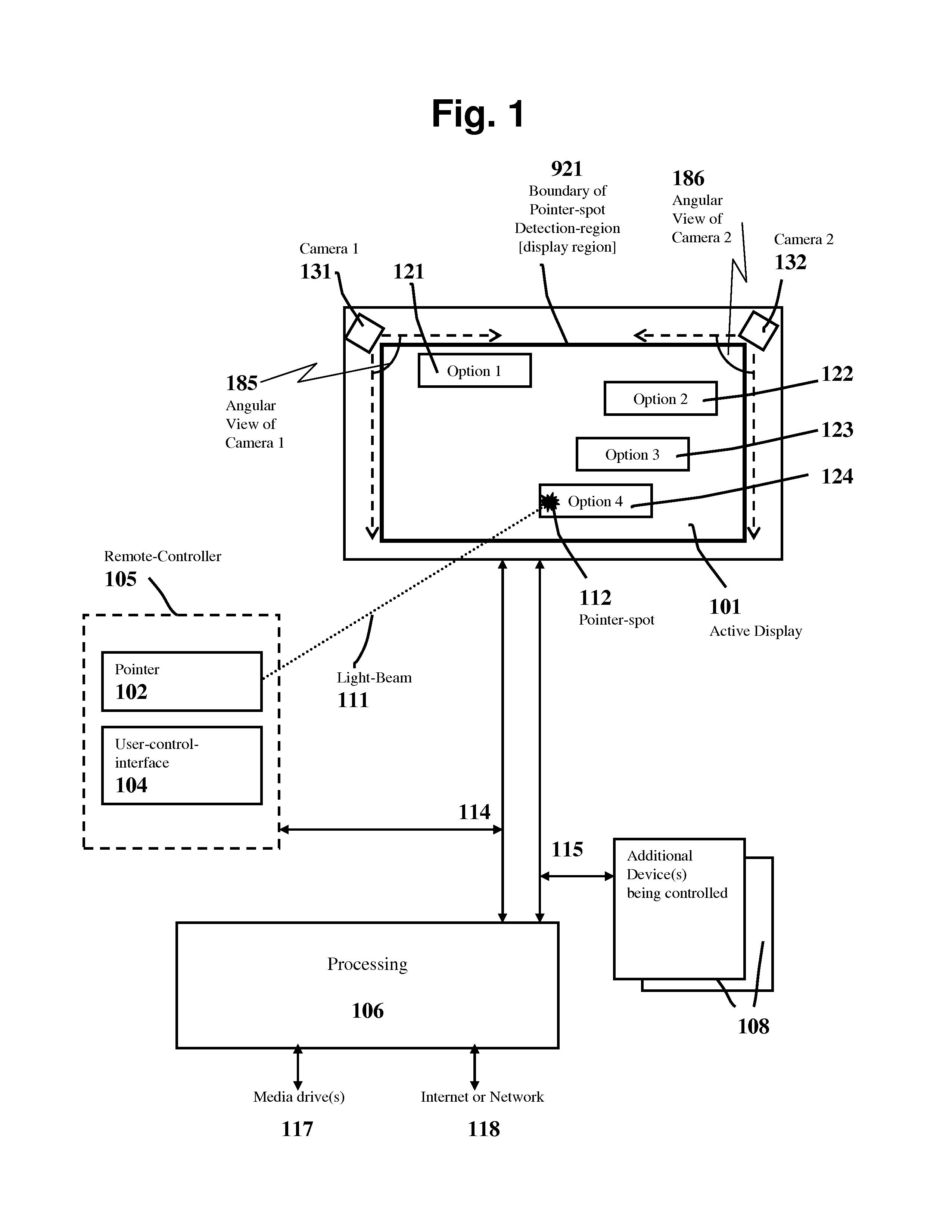
[0077]FIG. 1 illustrates a functional overview of one particular embodiment of remote-control and / or interactive-control. The remote-controller 105 may include a pointer 102 that emits light-beam 111 that may form a pointer-spot 112 on / near objects within a pointer-spot detection-region 921. The user may orient the remote-controller 105 to move the pointer-spot 112 in-order to select and / or interact-with objects that appear within the pointer-spot detection-region 921.

[0078]In the embodiment shown in FIG. 1, an active-display 101 is within the pointer-spot detection-region 921. In the embodiment shown in FIG. 1, detectors and / or imagers (cameras 131 and 132) may be aligned to the display so that the imagers may detect the pointer-spot 112 when it is at any location with the display 101. In the particular embodiment shown in FIG. 1, the cameras (131&132) have an appr...


PUM


Abstract

An apparatus and method for the remote control and / or interaction-with electronic-devices such as computers; home-entertainment-systems; media-centers; televisions; DVD-players; VCR-players; music systems; appliances; security systems; toys / games; and / or displays. A user may orient a pointer (e.g., laser pointer) to place a pointer-spot on / near object(s) on an active-display(s); and / or a fixed-display(s); and / or on real-world object(s) within a display region or pointer-spot detection-region. Detectors, imager(s) and / or camera(s) may be connected / attached to the display region and / or a structure that is connected / attached to display region. When the user initiates a “select”, the detectors / cameras may detect the location of the pointer-spot within the display region. Corresponding to the user's selection(s); control action(s) may be performed on the device(s) being controlled / interacted-with and additional selection-menus may be optionally presented on an active-display.

Description

CROSS REFERENCE TO RELATED APPLICATIONS[0001]This application is a continuation-in-part of U.S. application Ser. No. 11 / 563,785, filed on Nov. 28, 2006, originally entitled “Remote Control and Interaction using Pointer(s) and Display Detectors”. This earlier application in its entirety is incorporated by reference into this specification.BACKGROUND OF INVENTION[0002]1. Field of the Invention[0003]This invention relates to the remote control-of and / or interaction-with electronic-devices such as computers; home-entertainment-systems; media-centers; televisions; DVD-players; VCR-players; music systems; displays; appliances; security systems; games / toys; or any other type of device that user(s) may control or interact with.[0004]2. Description of Related Art[0005]Current remote controls are complex to use because of the large number of control-buttons they have. Two examples of prior art remote controllers are shown in FIG. 0a. Some remotes have over 50 physical buttons. In addition, so...

Claims


Application Information

Patent Timeline
Patent Type & Authority Patents(United States)
IPC IPC(8): G09G5/00
CPCG06F3/0304G06F3/0386H04N5/4403H04N21/4131H04N21/42206H04N21/6582H04N21/4223H04N21/4227H04N21/43615H04N21/4363H04N21/6543G06F2203/0331H04N21/42207H04N21/42204H04N21/41265
Inventor WIEDER, JAMES W.
Owner SYNERGYZE TECH LLC
Why Eureka
Try Eureka