Combination castor whose castor units are braked simultaneously

a technology of simultaneous brakes and castors, applied in the direction of castors, brake element arrangements, vehicle components, etc., can solve the problems of inconvenient user locking and unlocking the castors, and achieve the effect of enhancing the versatility of the combination castor, reducing the number of castor units, and controlling the castor units easily and quickly

Inactive Publication Date: 2013-08-27
SUNNY CASTORS
View PDF41 Cites 11 Cited by
  • Summary
  • Abstract
  • Description
  • Claims
  • Application Information

AI Technical Summary

Benefits of technology

[0007]According to the primary advantage of the present invention, when the pedal is stepped by a user, the propeller shaft is driven to rotate the at least one rotation plate which drives the at least two links to operate the at least two castor units so as to brake or position the at least two castor units simultaneously.
[0008]According to another advantage of the present invention, the user only needs to tread the pedal so as to operate the castor units simultaneously so that the user can control the castor units easily and quickly.
[0009]According to a further advantage of the present invention, the linking unit may include multiple rotation plates and multiple links to control multiple castor units so that the number of the castor units can be increased and decreased freely, thereby enhancing the versatility of the combination castor.
[0010]Further benefits and advantages of the present invention will become apparent after a careful reading of the detailed description with appropriate reference to the accompanying drawings.BRIEF DESCRIPTION OF THE SEVERAL VIEWS OF THE DRAWING(S)
[0011]FIG. 1 is a perspective view of a combination castor in accordance with the preferred embodiment of the present invention.
[0012]FIG. 2 is an exploded perspective view of the combination castor as shown in FIG. 1.

Problems solved by technology

However, the castors are controlled by the braking devices respectively so that a user has to lock each of the braking devices respectively so as to brake and position each of the castors and has to unlock each of the braking devices respectively so as to release each of the castors, thereby greatly causing inconvenience to the user when locking and unlocking the castors.

Method used


Image

  • Combination castor whose castor units are braked simultaneously
  • Combination castor whose castor units are braked simultaneously
  • Combination castor whose castor units are braked simultaneously

Examples


Embodiment Construction

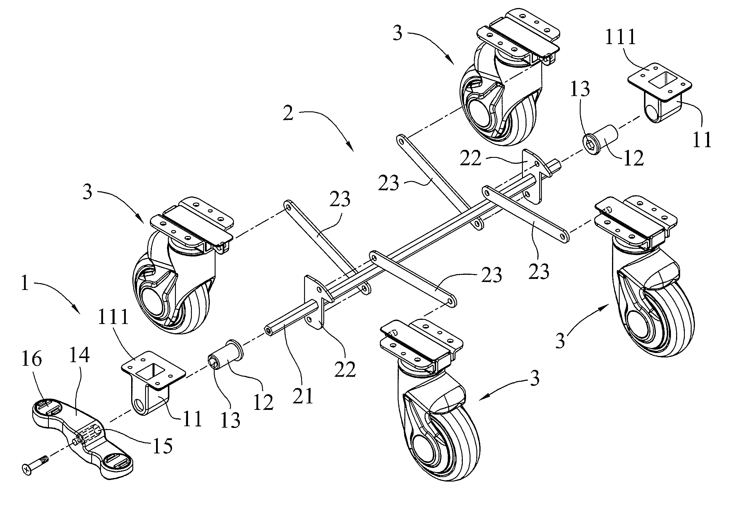
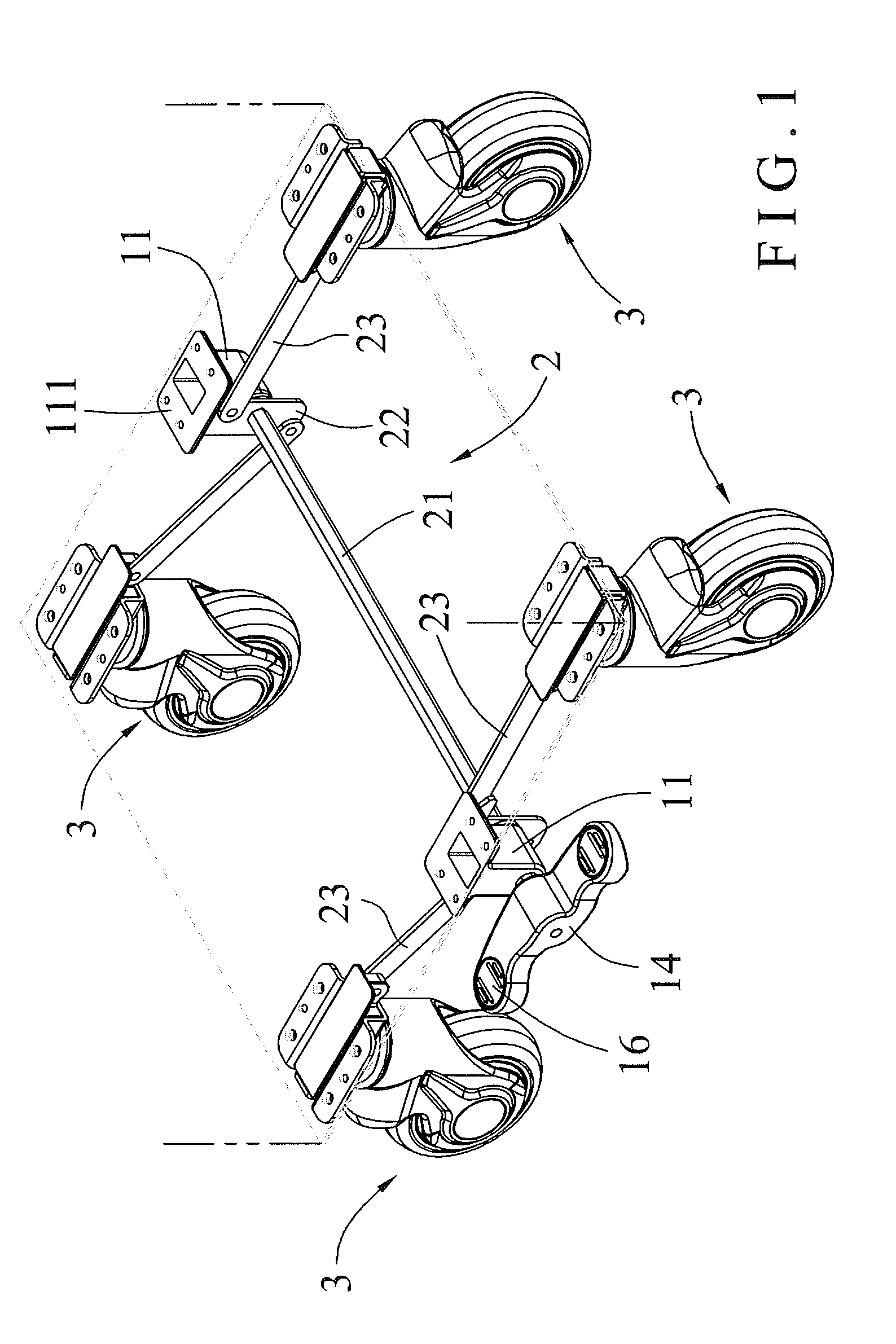
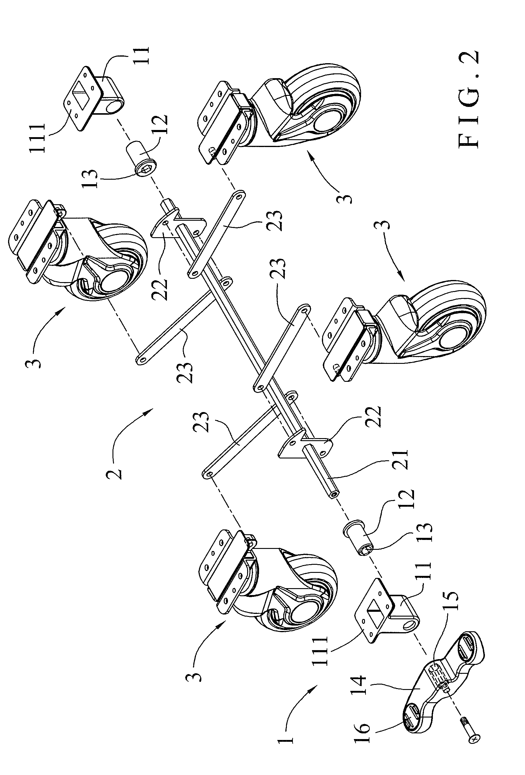
[0018]Referring to the drawings and initially to FIGS. 1-5, a combination castor in accordance with the preferred embodiment of the present invention comprises a control unit 1, a linking unit 2 connected with the control unit 1, and at least two castor units 3 connected with the linking unit 2.

[0019]The control unit 1 includes at least one mounting seat 11, at least one bushing 12 mounted in the at least one mounting seat 11 and having an interior provided with a mounting hole 13, and a pedal 14 pivotally mounted on a side of the at least one mounting seat 11 and having an interior provided with a driving hole 15 aligning with the mounting hole 13 of the at least one bushing 12.

[0020]The at least one mounting seat 11 of the control unit 1 is attached to the bottom of an object, such as a cart, stroller, chair and the like. The at least one mounting seat 11 of the control unit 1 has a top provided with a top plate 111 secured to the bottom of the object. The mounting hole 13 of the ...


PUM


Abstract

A combination castor includes a control unit, a linking unit, and at least two castor units. The control unit includes at least one mounting seat, at least one bushing mounted in the at least one mounting seat, and a pedal pivotally located at a side of the at least one mounting seat. The linking unit includes a propeller shaft extended through the at least one bushing and locked onto the pedal, at least one rotation plate secured on the propeller shaft, and at least two links each pivotally connected with the at least one rotation plate and the respective castor unit. Thus, when the pedal is stepped, the propeller shaft is driven to rotate the at least one rotation plate which drives the links to operate the castor units so as to brake or position the castor units simultaneously.

Description

BACKGROUND OF THE INVENTION[0001]1. Field of the Invention[0002]The present invention relates to a wheeled vehicle and, more particularly, to a combination castor for a cart, stroller, chair and the like.[0003]2. Description of the Related Art[0004]A conventional wheeled vehicle, such as a cart, stroller, chair and the like, comprises a main frame, a plurality of castors mounted on the bottom of the main frame, and a plurality of braking devices mounted on a respective one of the castors to brake and position each of the castors. However, the castors are controlled by the braking devices respectively so that a user has to lock each of the braking devices respectively so as to brake and position each of the castors and has to unlock each of the braking devices respectively so as to release each of the castors, thereby greatly causing inconvenience to the user when locking and unlocking the castors.BRIEF SUMMARY OF THE INVENTION[0005]In accordance with the present invention, there is ...

Claims


Application Information

Patent Timeline
Patent Type & Authority Patents(United States)
IPC IPC(8): B60B33/02
CPCB60B33/0092B60B33/0081
Inventor LIN, MING-HSIENYANG, FENG-HSI
Owner SUNNY CASTORS
Why Eureka
Try Eureka