The RF signal can, however, be seriously degraded during signal transmission.
The effect of signal loss is exacerbated by the noise and interference introduced into the signal along the communication path.
The noise and interference can be particularly problematic when introduced at the receiver where the communicated signal is weakest, thereby resulting in low signal-to-noise-and-interference ratio (SNIR) conditions and making signal decoding difficult.
In severe cases with low SNIR levels, the system can be prone to making decoding errors.
The problem of electromagnetic interference (EMI) is of interest because it can be considerably stronger than other noise sources and can thus be the dominant system impairment, or in other words, the active constraint limiting system performance.
To these unintended devices, those RF signals can be nuisance interference.
When such unintended signals are strong enough, they can overwhelm the desired received communications signal.
The concurrent use of two or more of these services in close proximity, however, can cause one service to interfere with another.
The technological advancement of communications devices is being impeded by increased interference not only because of the number of radios used in a confined area but also because of the denser and faster signal routing in newer communications devices.
Thus, even on devices where the radios are carefully controlled, e.g. there is no concurrent operation of multiple radio services, the operation of other non-radio aspects of the device during radio communication may pose a problem.
For example, in a camera-enabled mobile phone, a ribbon cable bus between a processor and camera module may emit enough EMI to disrupt phone reception resulting in the interruption of an ongoing call or the missing of an incoming call.
EMI can impede the integration of wireless radio services and other technologies involving high-speed signal paths into a single, small form factor device.
While such filters offer very high suppression of out-of-band interferers, their use has at least two significant drawbacks.
First, these high-quality filters commonly have undesirably high component costs, in terms of dollar pricing.
Second, these filters often come as discrete components which are not integrated into other existing components on a communications receiver.
Furthermore, the EMI problem is severe enough in many contexts that multiple filters have to be cascaded to provide adequate isolation, thus multiplying the price and area costs associated with that solution.
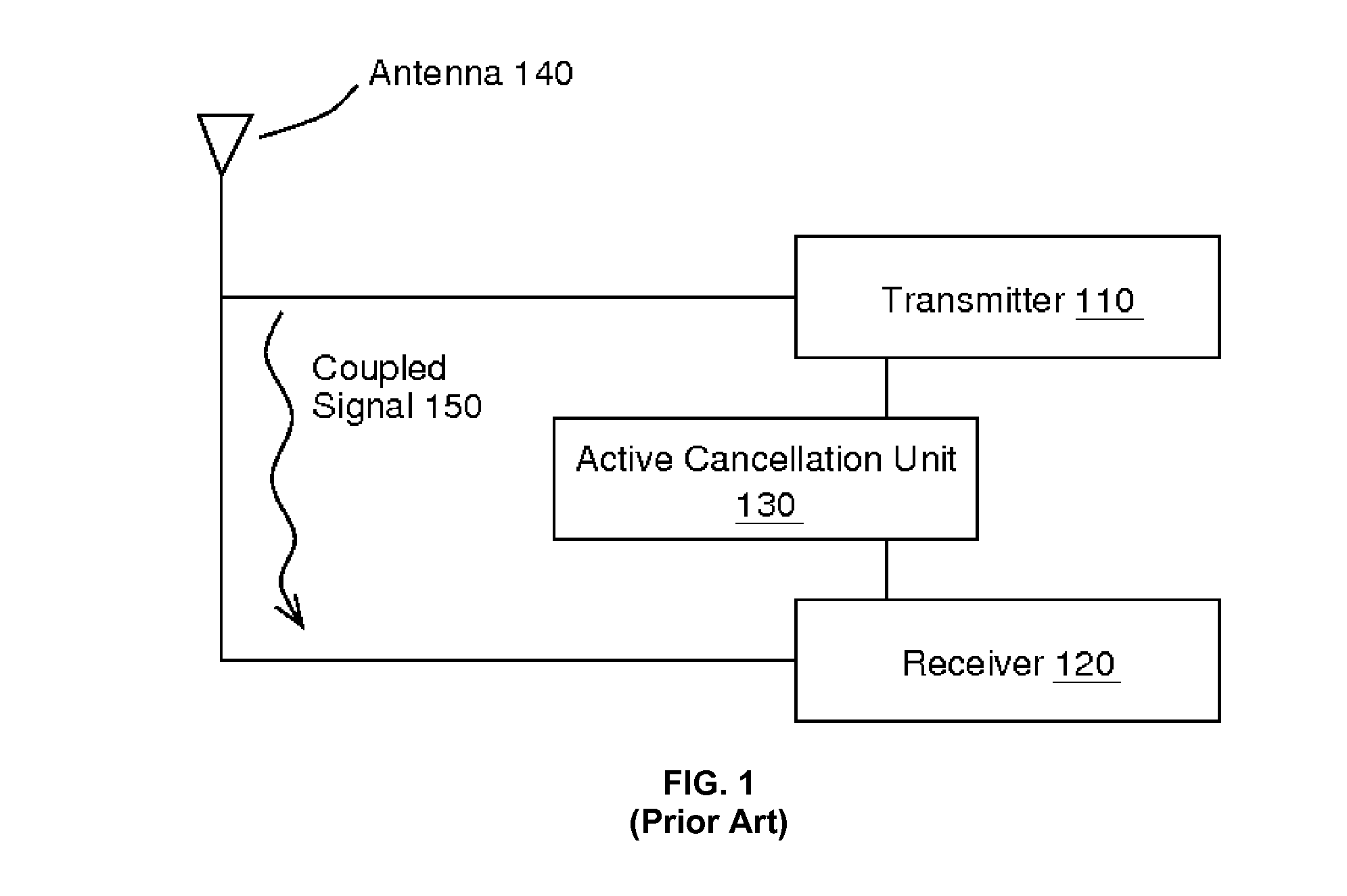
One significant drawback is the fundamental requirement that the active cancellation unit 130 senses (or equivalently taps or splits) the output of the aggressing transmitter 110 as proposed in U.S. Pat. No. 6,539,204 by Marsh and Sutton, U.S. Pat. No. 6,915,112 by Sutton and Soledade, U.S. Pat. No. 6,745,018 by Zehavi et al., U.S. Pat. No. 7,123,676 by Gebara et al., and U.S. Pat. No. 7,522,883 by Gebara et al.
However, such a sensing is highly undesirable and in many cases impossible.
Indeed, it is undesirable to sense the aggressing transmitter 110 output because doing so can distort the signal transmitted from the antenna 140.
However, the addition of a sensor on the transmit path could significantly alter the properties of the transmitted signal causing it to fail the requirements and thus necessitate a major, sometimes impractically laborious, redesign of the communications system.
In modern communications systems, there are myriad such buses that can cause problematic EMI and identification of the one or more offenders is impractical.
Even if the offending EMI sources could be identified, it would likely be impractical to sense them because of routing complexities from the sensing point to the victim receiver.
Such an approach is limited because it can only cancel interference from other CDMA signals, i.e. it does not mitigate interference from non-CDMA sources.
Furthermore, among CDMA interference sources, that approach only cancels those that are received at the same basestation as the victim receiver.
Such a cancellation technique is very limited in the types of communications systems to which it can benefit.
Another problem with methods for interference cancellation in the prior art pertains to those that require the aggressing transmitter 110 to have prior knowledge of the carrier frequency of the victim receive signal.
Requiring such knowledge is undesirable because in many situations aggressor-victim pairs cannot be known ahead of time and are constantly changing.
An additional problem with interference cancellation methods in the prior art relates to those that require modification of the aggressing transmit signal.
First, modifying the aggressing transmit signal after the output of an aggressing transmitter 110 is likely to disturb the signal integrity of the transmitted signal.
Such degradation may come in the form of loss of valuable signal power or in terms of signal distortion.
These degradations can be severe enough to cause the signal to violate required signal criteria such as those imposed by spectral masks.
Such high degrees of customization are not practical for large scale adoption and the variety of interference pairings that can be encountered.
Another drawback of modifying the transmitted aggressor signal is that doing so requires identification of and physical access to the interference source.
As previously noted, in many contexts, the aggressing source is not known or not on the same device as the victim receiver and thus not available for modification.
Unfortunately, in many cases, the identity of the aggressing transmitter, and especially its operating frequency, is not known to the victim receiver.
Furthermore, as known to those skilled in the art, the act of injecting a tone, or any other signal, into the received victim path can degrade the signal fidelity of the already weak and vulnerable received victim signal.
Oftentimes, such a fidelity measure is not available externally from the receiver 120 for such use, and even in cases where it is available, making use of the signal can be burdensome due to the extra routing or processing resources needed.
Second, indirect measures such as received power or RSSI are not always indicative of interference power or lack thereof.
For example, the amount of residual interference (after cancellation) may increase while the received victim power degrades due to a fading communications channel.
Besides the inappropriateness of general fidelity measures for the control of an interference cancellation unit, many methods in the prior art propose the less than desirable optimization technique of trial-and-error coordinate descent optimization.
The drawback of trial-and-error coordinate descent minimization is that the cancellation unit is always forced to test a parameter set which will have an unknown and perhaps worse performance.
However, removing interference at the baseband level has several major drawbacks.
Such an approach places extreme performance requirements on the front-end circuitry components of the receiver.
In particular, when a weak received victim is in the presence of a strong interferer, the down-conversion mixer in the receiver will oftentimes further distort the signal as nonlinearities are introduced due to practical limitations on circuit linearity.
Furthermore, because the interference signal is so much larger than the received victim signal, most of the dynamic range of the ADC is wasted to accommodate the large interferer.
Thus, either very expensive high performance front-end circuit components are required or additional signal degradation is introduced.

