Heading determination using sensors mounted on rotatable assembly

Active Publication Date: 2013-08-27
MOOG INC
View PDF74 Cites 17 Cited by
  • Summary
  • Abstract
  • Description
  • Claims
  • Application Information

AI Technical Summary

Benefits of technology

[0008]In one embodiment, the estimated error of the heading of the vehicle in the dynamic state is computed by computing a state cova

Problems solved by technology

Thus, these sensors are subject to local magnetic disturbance.
However, arbitrary time-varying magnetic disturbance is common and can cause significant heading measurement error.
Such models are limited in accuracy because they do not account for local geographic mass distribution and cannot precisely predict the change to Earth's magnetic field in the future.
Therefore, the heading determined based on the GNSS systems

Method used


Image

  • Heading determination using sensors mounted on rotatable assembly
  • Heading determination using sensors mounted on rotatable assembly
  • Heading determination using sensors mounted on rotatable assembly

Examples


Embodiment Construction

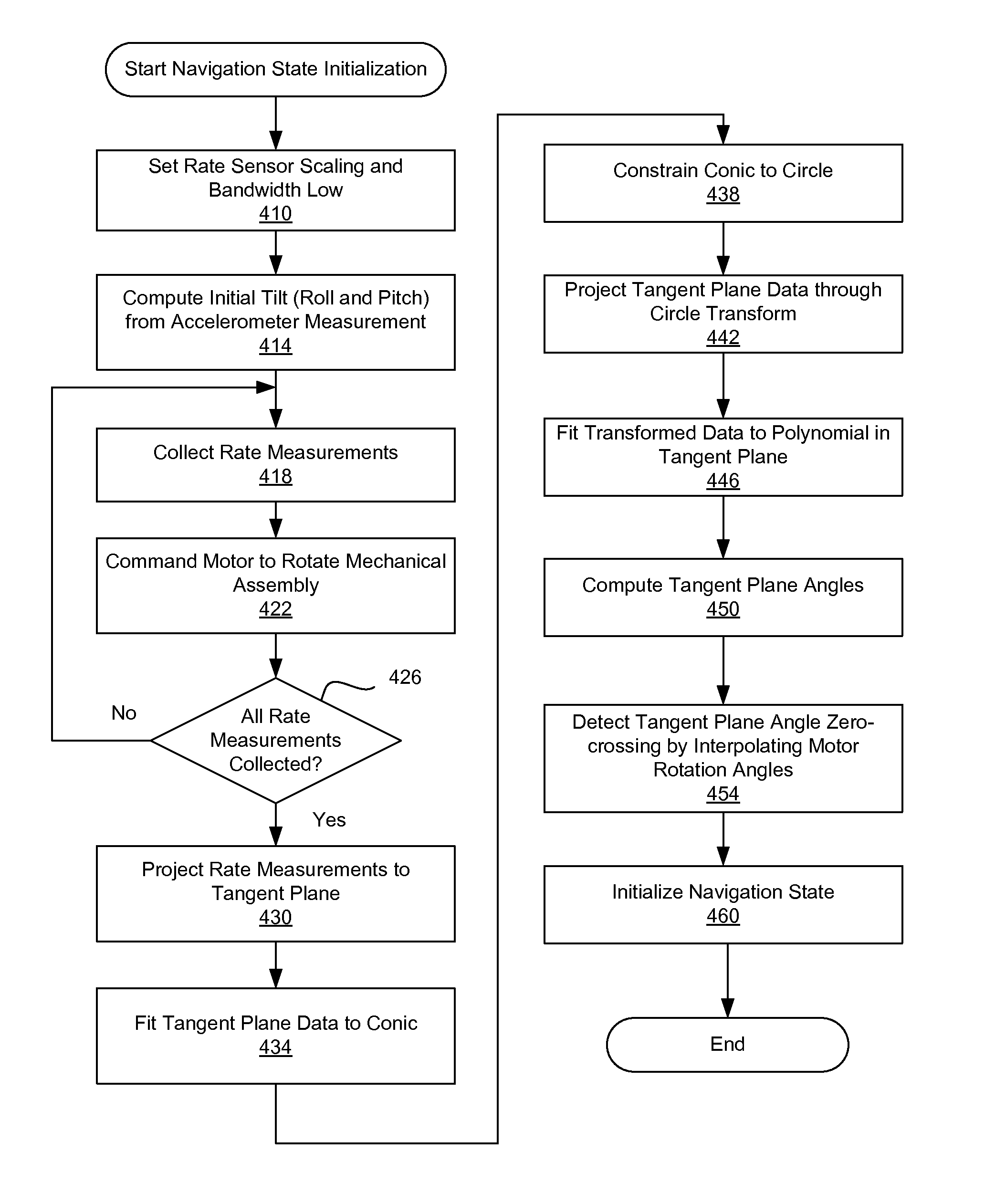
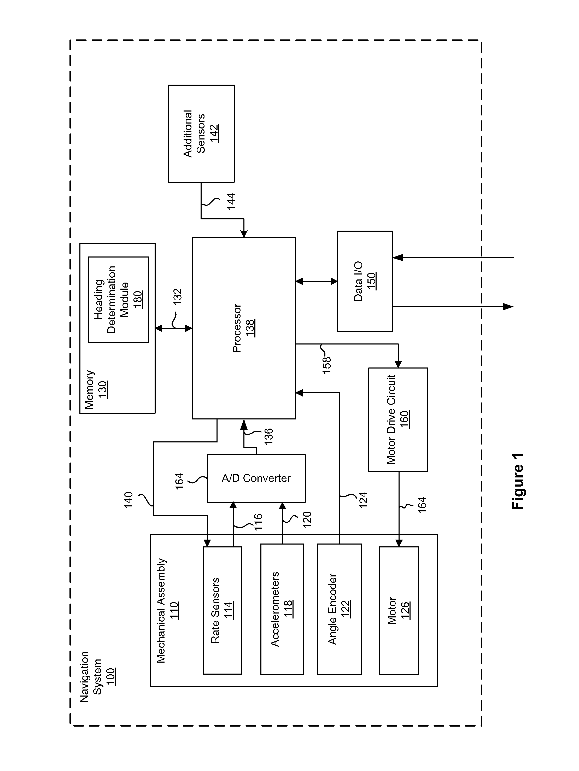
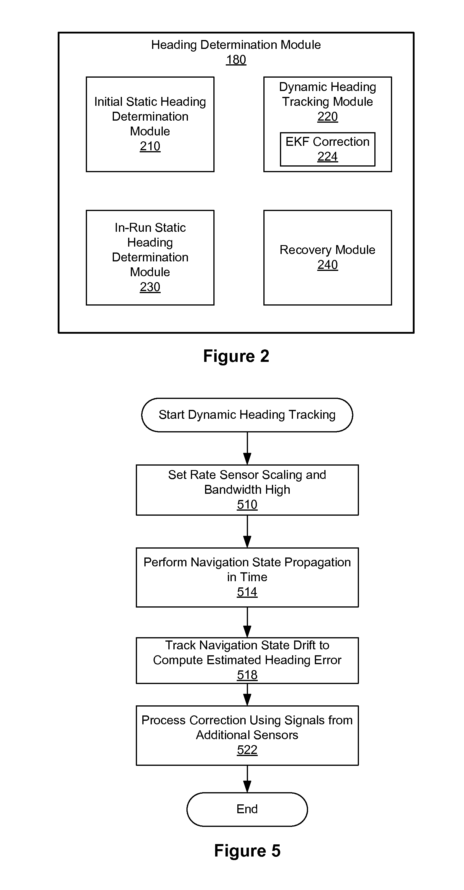
[0017]Embodiments of the invention relate to a system and method for more accurately and robustly determining the heading of a vehicle by taking measurements of angle rates by rate sensors mounted on a movable mechanical assembly. In a quasi-static state of the vehicle, the mechanical assembly is rotated around axes perpendicular to the tangent plane of the Earth, and angle rates are measured by the rate sensors at different rotational angles of the mechanical assembly. The measurements of the angle rates are then computed to determine the initial heading of the vehicle relative to a true north of the Earth in the quasi-static state of the vehicle. After determining the initial heading, navigation state propagation is performed to determine the heading of the vehicle in a dynamic state of the vehicle. By taking measurements of the rate sensors at different rotation angles of the mechanical assembly and performing computation based on the measurements, the heading of the vehicle rela...


PUM


Abstract

A system and method for more accurately and robustly determining the heading of a vehicle by taking measurements of angle rates using rate sensors mounted on a movable mechanical assembly. In a quasi-static state of the vehicle, the mechanical assembly is rotated around axes perpendicular to the tangent plane of the Earth, and angle rates are measured by the rate sensors at different rotational angles of the mechanical assembly. The measurements of the angle rates are then computed to determine the initial heading of the vehicle relative to the true north of the Earth in the quasi-static state of the vehicle. After determining the initial heading, navigation state propagation is performed to determine the heading of the vehicle in non-quasi-static state of the vehicle. By taking measurements of the rate sensors at different rotation angles and performing computation, the heading of the vehicle relative to the Earth's true north can be determined using less accurate angle sensors.

Description

FIELD OF THE INVENTION[0001]This invention relates to estimating the navigation state of accelerating bodies, more specifically to estimating attitude, heading and other navigational states using solid-state rate sensors.BACKGROUND OF THE INVENTION[0002]In a variety of navigation applications, it is necessary to determine the heading of an accelerating object. The heading of an object is the direction the object is pointing. For example, a robotic airplane may require heading information and other vehicle state information to point a camera at a target, navigate to a destination, and otherwise control its movement. Conventional systems measure heading using a traditional floating magnetic compass or strap-down magnetic vector sensor to measure the Earth's magnetic field. However, these sensors respond to any magnetic field. Thus, these sensors are subject to local magnetic disturbance. Many techniques exist for calibrating out local magnetic disturbance that is non-time variant with...

Claims


Application Information

Patent Timeline
IPC IPC(8): G01C21/18
CPCG01C21/18G01C25/005
Inventor LICCARDO, DARREN S.JAMES, JOHN J.STOCKWELL, WALTER K.HORTON, MICHAEL A.
Owner MOOG INC
Why Eureka
Try Eureka