
Square baler with an improved bale chute

a baler and bale chute technology, applied in the field of agricultural square balers, can solve the problems of affecting the quality of baler, the risk of bales being damaged by falling from the baling chamber, and the impact of the bale too large,

Active Publication Date: 2013-09-03
BLUE LEAF I P INC
View PDF7 Cites 1 Cited by
  • Summary
  • Abstract
  • Description
  • Claims
  • Application Information

AI Technical Summary

Benefits of technology

The present invention is about a baler that can make bales safely and easily lower them onto the ground without leaving the driver cab. A lever mechanism is used to move the bale chute from one stable position to another. This mechanism has a unique action that allows for smooth and efficient operation. The technical effect of this invention is to make baling more efficient and safe.

Problems solved by technology

Because the discharge end of the baling chamber is at a substantial height above the ground, there is a risk of bales being damaged by their fall from the baling chamber.
For example, the impact may result in breakage of some or all of the strands.
On the other hand too high an exit level of the chute makes the impact of the bale too great, such that it may fall apart.
Even with reduced heights, problems may occur because the bale starts rotating during its fall and the acquired momentum may rotate the bale further after its edge hits the ground, thereby making the bale tip over and putting it to rest on its front end.
The consequent mixture of properly deposited and upright bales on the same field later complicates the handling and collection of the bales.
Such reversing of the baler is hazardous and not always successful.
Alternatively, the operator would need to descend from his cabin and push the bale manually along the bale chute but this is inconvenient.

Method used


Image

  • Square baler with an improved bale chute
  • Square baler with an improved bale chute
  • Square baler with an improved bale chute

Examples


Embodiment Construction

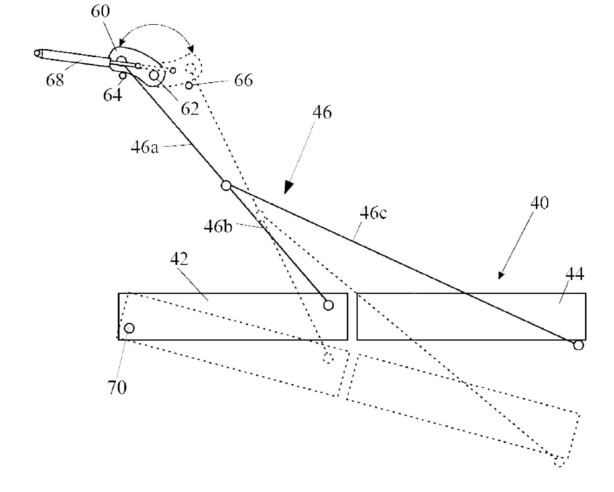
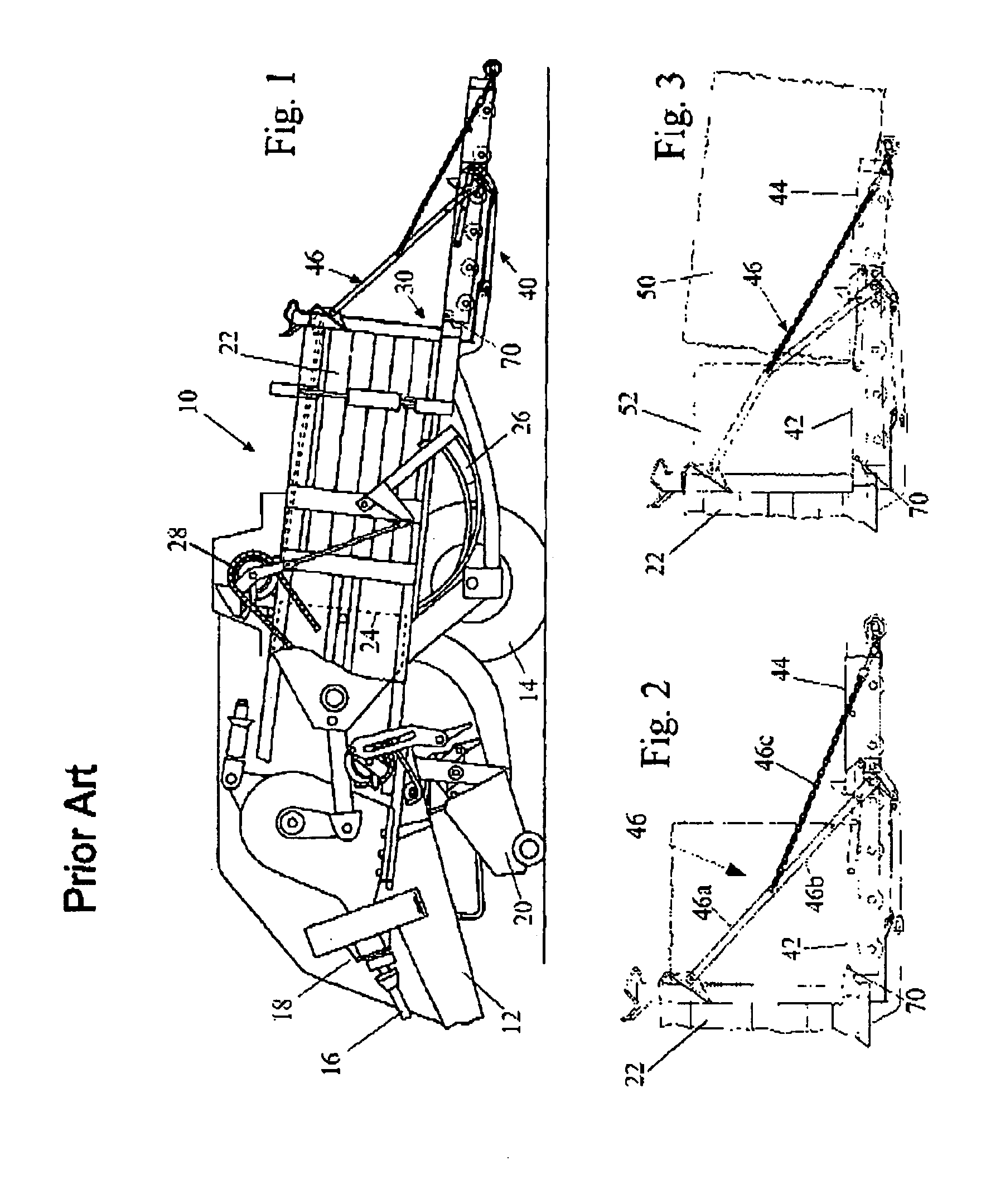
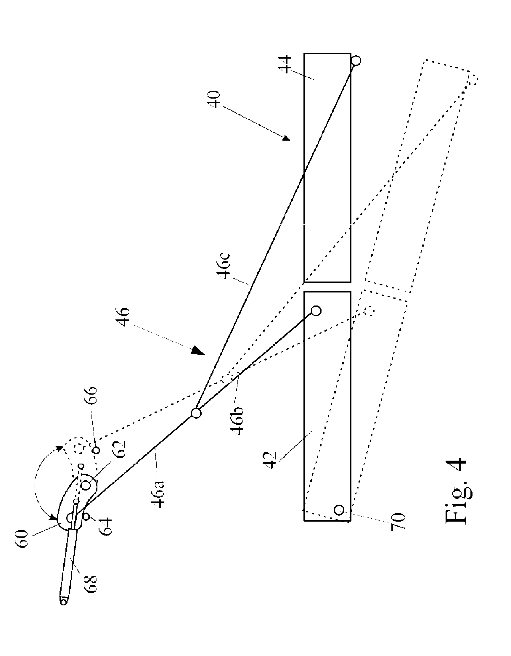
[0025]FIGS. 1 to 3 are the same as FIGS. 1 to 3 of EP 0974260 in which they are described fully. In the interest of brevity, the latter specification is imported herein by reference in its entirety and the figures will be described below only to the extent necessary for an understanding of the present invention.

[0026]The baler 10 is hitched at its front end 12 to a tractor and is supported on wheels 14. The baler 10 is powered from the power take off shaft of the tractor through an input shaft 16 of a gearbox 18.

[0027]Crop lying in a field in windrows is collected from the ground by a pickup 20 and is transferred in individual pre-compressed slices into a baling chamber 22 in which it is compressed further by a constantly reciprocating plunger 24. When the compressed crop package in the baling chamber reaches the desired length, needles 26 and knotters 28 tie strands around the package to form a bale. The completed bale remains in the baling chamber 22 and is incrementally pushed ou...


PUM


Abstract

A square baler comprises a bale chute for lowering completed bales onto the ground, wherein the bale chute has a leading end connected to the rear end of the baler for pivoting movement between a raised transport position and a lowered operating position about an axis transverse to the direction of travel of the baler, and a suspension is provided. The suspension is connected to the baler by way of a lever mechanism that is movable between a first position in which the bale chute is supported in the operating position and a second position in which the bale chute is inclined sufficiently to the horizontal to cause a bale resting on any part of the bale chute to slide under the action of gravity along the bale chute and to fall onto the ground from the trailing end of the bale chute.

Description

[0001]This application is the US National Stage filing of International Application Serial No. PCT / EP2010 / 056830 filed on May 18, 2010 which claims priority to Belgium Application BE2009 / 0314 filed May 19, 2009, each of which is incorporated herein by reference in its entirety.TECHNICAL FIELD[0002]The present invention relates to an agricultural square baler for picking up crop material such as hay or straw from a field and forming it into rectangular bales. More particularly the invention relates to a bale chute located at the rear of the baler for receiving the formed bales and depositing them onto the ground.BACKGROUND ART[0003]Conventionally, agricultural balers comprise a wheeled frame which is towed by a tractor over a field to pick up hay, straw or silage grass and to feed such crop material to a baling chamber in which it is compressed into a rectangular package under the action of a reciprocating plunger. When each package has reached a predetermined length, a tying mechani...

Claims


Application Information

Patent Timeline
Patent Type & Authority Patents(United States)
IPC IPC(8): A01F15/08B30B15/32B30B9/30
CPCA01F15/0875
Inventor LAMMERANT, EDDYSCHOONHEERE, MARNIX J.VANDE RYSE, JOHAN A. E.
Owner BLUE LEAF I P INC
Learn More