
Lowering device comprising a support structure

a technology of lowering device and support structure, which is applied in the direction of machine supports, building scaffolds, auxiliary members of forms/shuttering/falseworks, etc., can solve the problem of inability to open inadvertently the inventive locking mechanism, and achieve the effect of improving the invention of lowering device, quick and safe mounting, and quick and safe lowering

Active Publication Date: 2009-01-06
PERI GMBH
View PDF10 Cites 0 Cited by
  • Summary
  • Abstract
  • Description
  • Claims
  • Application Information

AI Technical Summary

Benefits of technology

[0005]It is the object of the invention to provide a lowering device which can be moved in a safe, simple and rapid manner into a first working position and a second lowered position.SUMMARY OF THE INVENTION
[0009]Safe lowering can thereby be advantageously ensured with a very simple structure.
[0011]When the plate is stationary, this structure permits safe lowering of the support structure connected to the lowering device in dependence on the design of the two support surfaces of the second latch part and their separation from the axis of rotation of the second latch part. Lowering is possible only to the extent allowed by the matching support surfaces on the second latch part.
[0013]This is advantageous in that the locking mechanism can be triggered, i.e. be opened with only little force using an aid, e.g. a rod that can be inserted into the opening. The latch parts formed in the locking mechanism are pivoted and turned into a second end position, which limits the lowering motion of a support structure connected to the lowering device.
[0015]This embodiment of the inventive lowering device permits connection of a conventional construction support to the lowering device in a torsion-proof and bending-resistant fashion. If the lowering device is mounted to a construction support in this fashion, the support structure connected to the lowering device can be lowered rapidly and safely by an amount predetermined by the locking mechanism.
[0016]The frame advantageously forms a housing which receives both the bracket and the plate, and comprises receptacles for a support for immovably connecting the lowering device to the support. A construction support can be quickly and safely mounted to the lowering device via such receptacles.

Problems solved by technology

In its first position, the locking mechanism is self-locking under load, such that inadvertent opening of the inventive locking mechanism is not possible.

Method used


Image

  • Lowering device comprising a support structure
  • Lowering device comprising a support structure
  • Lowering device comprising a support structure

Examples


Embodiment Construction

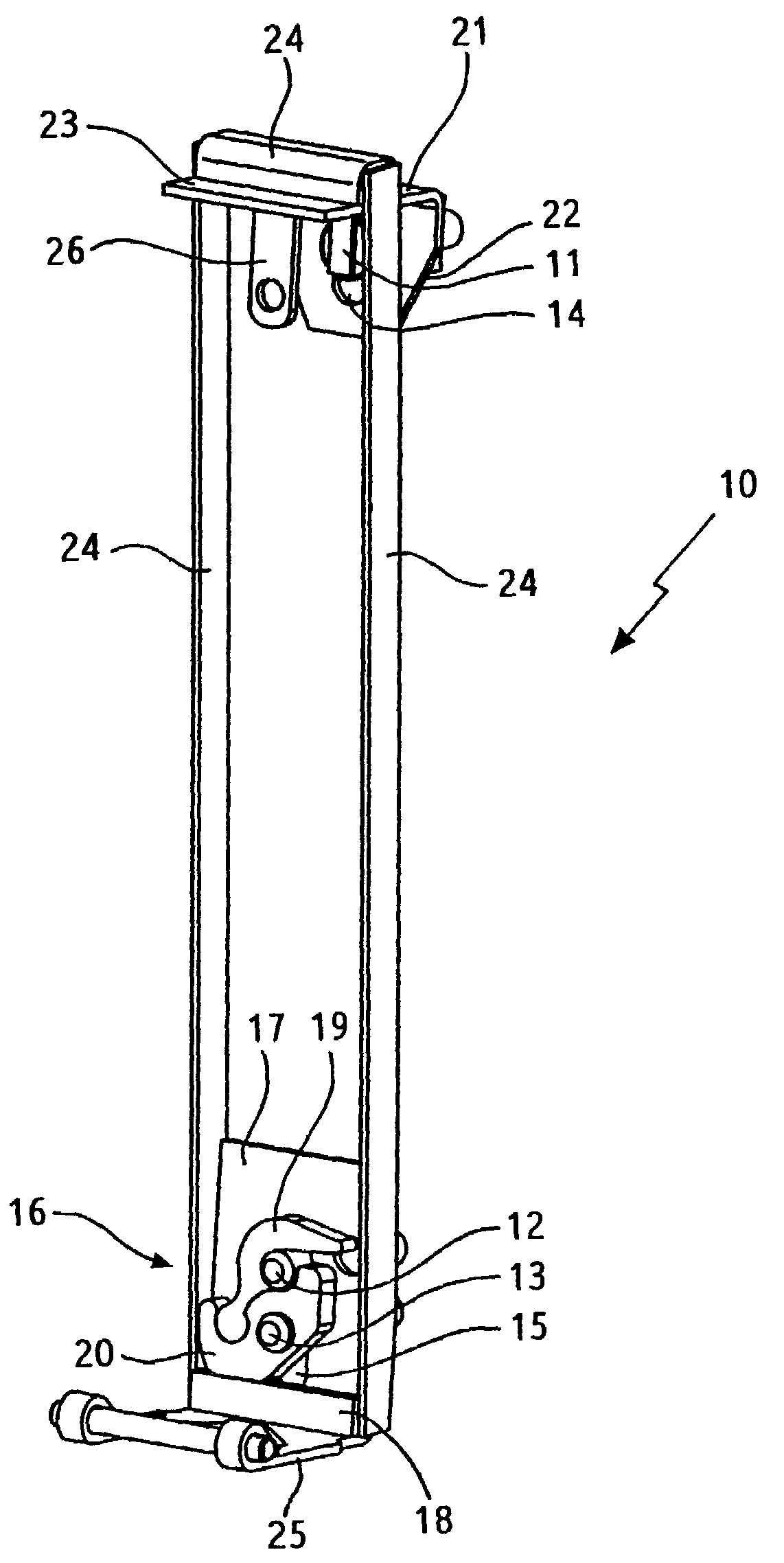
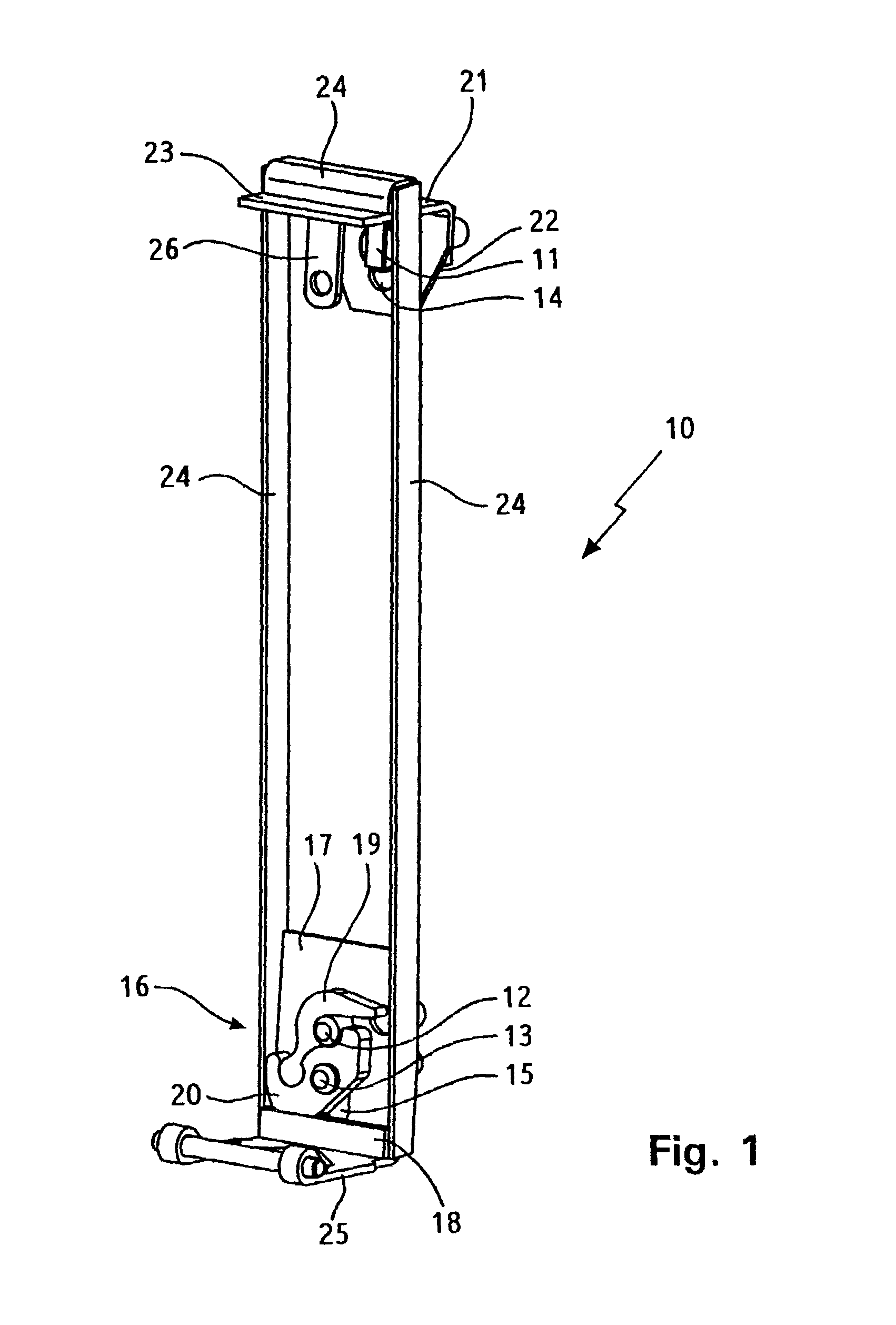
[0026]FIG. 1 shows a lowering device 10 which can be mounted to a construction support (not shown) and to a support structure (also not shown in the figure). The lowering device 10 is connected to a support structure via bolts 11, 12, 13. The sections of the bolts 11, 12, 13 facing away from the support structure penetrate through a first elongated hole 14 and a second elongated hole 15 of the lowering device 10. The bolts 11, 12, 13 and the support structure connected thereto can be displaced along the elongated holes 14, 15 when a locking mechanism 16 of the lowering device 10 is opened.

[0027]The locking mechanism 16 comprises a plate 17 with a projection or stop 18, a first latch part 19, a second latch part 20 and the bolts 12, 13. The first and second latch parts 19, 20 can be pivoted or turned about the bolts 12, 13. The second latch part 20 is supported on the projection 18 both in a first and in a second location of the locking mechanism 16. FIG. 1 shows the locking mechanis...


PUM


Abstract

The invention relates to a lowering device (10) for the construction industry, which comprises a support structure. The lowering device comprises a plate (17) holding a locking mechanism (16) and blocking or releasing the mobility of bolts (12, 13). The bolts (12, 13) are firmly linked with a support structure and are fastened on the locking mechanism (16) in a controlled manner to such an extent that, in a first position, the support structure linked with the lowering device (10) is lifted and, in a second position of the locking mechanism, the support structure linked therewith is lowered as much as the locking mechanism permits.

Description

[0001]This application is the national stage of PCT / DE2004 / 00427 filed on Nov. 3, 2004 and claims Paris Convention priority of DE 103 51 255.1 filed Nov. 3, 2003.[0002]The invention concerns a lowering device for a support structure for safely lowering all building industry loads.[0003]Support structures for the building industry, such as ceiling formwork elements or floor tables are conventionally held by construction supports with adjustable length, which are adjusted to a predetermined length for a concrete pouring process. For example, a large number of construction supports, e.g. floor tables, are used for concrete pouring of large ceiling sections. When the ceiling to be poured with concrete has hardened to a sufficient degree, the formwork must be removed from the ceiling by shortening e.g. all telescopic construction supports which support the ceiling formwork until the formwork elements or floor tables can be removed and re-used at another location.[0004]The removal of the ...

Claims


Application Information

Patent Timeline
IPC IPC(8): E04G25/00E04G17/00E04G11/48
CPCE04G11/483E04G11/486E04G11/48
Inventor SCHWOERER, ARTUR
Owner PERI GMBH
Learn More