
Servicing system and method for servicing a brake device of a brake system having a horizontally arranged brake disc

a technology of brake system and brake disc, which is applied in the direction of axially engaging brakes, motors, wind energy generation, etc., can solve the problems of large amount of effort, serious reduction of wind turbine efficiency, so as to reduce health and safety risks, reduce weight and torque, and the effect of strong and rigid

Active Publication Date: 2019-01-29
S B PATENT HLDG
View PDF21 Cites 0 Cited by
  • Summary
  • Abstract
  • Description
  • Claims
  • Application Information

AI Technical Summary

Benefits of technology

[0019]In an advantageous embodiment, the guiding means are designed and adapted to allow said part of the brake device to move between a first position, wherein said part is mounted in an operating position on the brake disc, and a second position, wherein said part can be serviced or removed from the brake disc. Accordingly, the entire servicing of the part of the brake device may be carried out, while the part is secured to the frame of the servicing system, which reduces the health and safety risks significantly compared to conventional servicing tools and methods.
[0020]In an advantageous embodiment, said part of the brake device is a yoke of a brake calliper. Once, the yoke has been secured to the frame of the servicing system, the yoke can be detached or disassembled from the brake device, whereby only the yoke may be moved to the servicing position on the frame. This lowers the weight and torque that the frame needs to support or carry during service.
[0021]The mounting means may advantageously comprise a clamp, such as a screw clamp, and / or a locking cam for clamping the frame on the brake disc. In principle, it is also possible for the mounting means to clamp to other parts of the brake system or yaw system, such as for instance a part of the yaw system. However, it is particularly advantageous to mount the frame to the brake disc, since the brake disc is always in a known position. Additionally, the brake disc is a strong and rigid structure that can easily support the weight of the frame and the brake device. Further, the brake disc is obviously located at the right height for removing and installing brake devices on the brake disc.
[0022]In another advantageous embodiment, the guiding means are adapted to allow said part of the brake device to move substantially parallel to a plane of the brake disc and substantially perpendicular to the yaw axis of the brake disc. Thereby, the part can be removed from the brake device and the brake disc without damage to any of the parts. However, it is also possible to design the guiding means so that the part is moved out of the plane of brake disc, e.g. in an angle relative to the plane of the brake disc or the yaw axis of the brake disc.
[0027]In another embodiment, the frame comprises a first mounting means for fixing the frame on a first side of the brake device and a second mounting means for fixing the frame on a second side of the brake device. This provides a servicing system, where the frame may securely be fixed to the brake disc and provides a secure base for carrying the part of the brake device or the entire brake device.
[0034]The frame may further be provided with a lifting device, such as a winch, for lowering or lifting said part relative to the frame. Accordingly, the part may safely be lowered onto for instance a work platform below the yaw brake system.

Problems solved by technology

If the wind turbine is not oriented correctly, the wind will impose uneven loads on the rotor and will seriously reduce the efficiency of the wind turbine.
One of the problems that is encountered with yaw brakes is the large amount of effort required, when the installed yaw brakes need to be removed from the brake disc for service, such as replacing brake pads or replacing the entire yaw brake.
The problems occur since the yaw brakes are typically arranged at quite a large distance from a working platform in the tower.
Further, the brakes are currently handled by a service technician, which includes lifting of the yaw brake from the brake disc and down to the working platform or vice versa, which in turn is associated with health and safety risks.
Additionally, current tools for assisting in lifting or lowering the yaw brakes are time-consuming to use, bulky and sometimes involve safety risks.
Another problem with current service methods and tools is encountered due the inherent design of brake callipers, which entails that the brake calliper has to be moved horizontally before being lowered.
The horizontal movement before lowering also involves safety risks in the current systems.
The service or replacement of parts of the brake is normally done at floor level, whereas the servicing tools are located at waist height, which again involves health and safety risks.

Method used


Image

  • Servicing system and method for servicing a brake device of a brake system having a horizontally arranged brake disc
  • Servicing system and method for servicing a brake device of a brake system having a horizontally arranged brake disc
  • Servicing system and method for servicing a brake device of a brake system having a horizontally arranged brake disc

Examples


Embodiment Construction

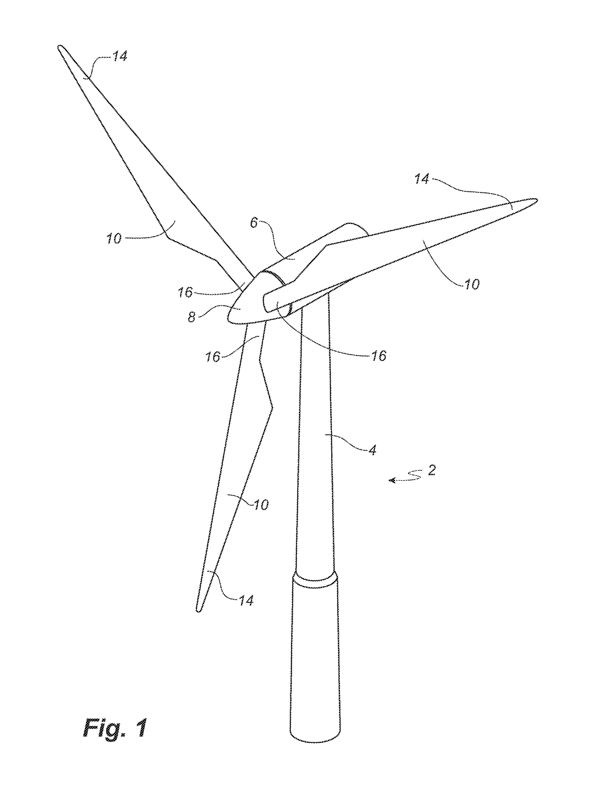
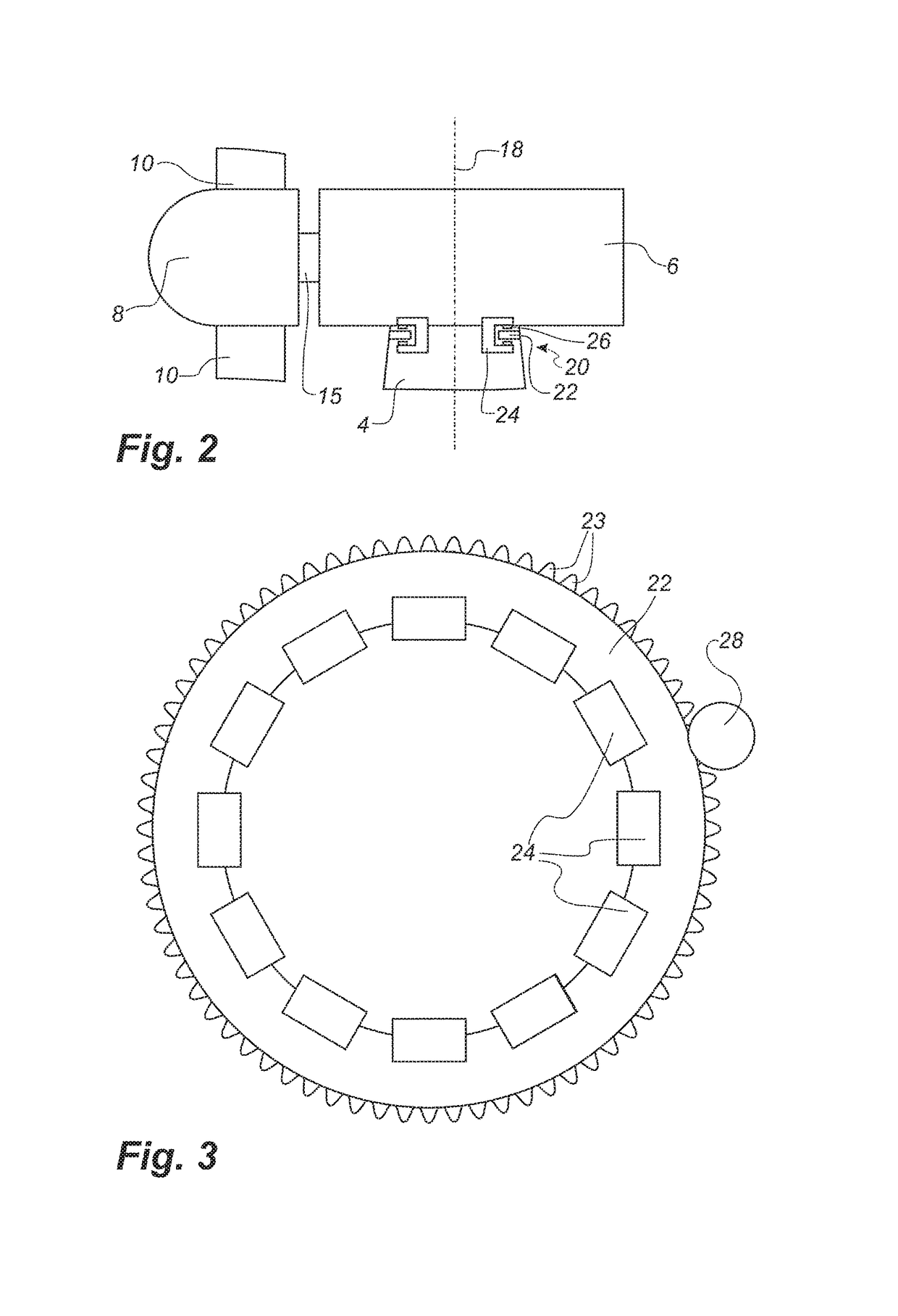
[0067]FIGS. 1 and 2 illustrate a conventional modern upwind wind turbine 2 according to the so-called “Danish concept” with a tower 4, a nacelle 6 and a rotor with a substantially horizontal rotor shaft 15. The rotor includes a hub 8 and three blades 10 extending radially from the hub 8, each having a blade root 16 nearest the hub and a blade tip 14 farthest from the hub 8. The rotor has a radius denoted R.

[0068]The wind turbine 2 comprises a yaw system, which controls the orientation of the wind turbine rotor relative to the prevailing wind direction. The yaw system allows the nacelle 6 or machine housing to be rotated around a vertical or yaw axis 18 relative to the tower 4. The yaw system may for instance comprise a yaw drive (not shown), e.g. in form of a gear, that may engage a toothed yaw bearing. The teeth may be provided on the inner ring or outer ring of the yaw bearing. The yaw drive is typically attached to the nacelle 6, whereas the yaw bearing is made stationary with re...


PUM


Abstract

A servicing system (30 or 300) for servicing a brake device (24) of a brake system comprising the brake device (24) and a brake disc (22) is described. The servicing system (30 or 300) includes a frame (32 or 302), and the servicing system (30 or 300) is further configured for mounting the frame (32 or 302) in a fixed position relative to the brake disc (22), supporting the brake device (24) to allow the brake device (24) to be moved on the frame (32 or 302) relative to the brake disc (22) and lifting the brake device (24) to allow the brake device (24) to be raised or lowered relative to the brake disc (22).

Description

TECHNICAL FIELD[0001]The present invention relates to a servicing system as well as a method for servicing a brake device of a brake system comprising the brake device and a brake disc.BACKGROUND[0002]A wind turbine comprises a tower and a nacelle or machine housing supported on the tower and carrying the blades, rotor and electricity producing parts. A yaw system controls the position of the nacelle relative to the tower about a vertically extending yaw axis to thereby control orientation of the wind turbine rotor relative to the prevailing wind direction. If the wind turbine is not oriented correctly, the wind will impose uneven loads on the rotor and will seriously reduce the efficiency of the wind turbine. Therefore, the function of the yaw system is important in order to improve the efficiency and prolong the lifetime of the wind turbine.[0003]The yaw system often comprises a toothed brake disc or ring fixed to the tower and a motor activated gear attached to the nacelle and me...

Claims


Application Information

Patent Timeline
Patent Type & Authority Patents(United States)
IPC IPC(8): B23P19/04F16D65/00F03D1/06F16D55/225B25B11/02F03D7/02
CPCF16D65/0043B25B11/02F03D1/06F03D7/0248F16D55/225Y02E10/721F05B2230/60F05B2230/80F16D2250/0084Y02E10/72
Inventor WOODS, JAMES A. W.LANG, MICHAEL
Owner S B PATENT HLDG
Learn More