Zoom lens

a zoom lens and lens body technology, applied in the field of zoom lenses, can solve the problems of anti-blur group, and large power consumption of the actuator

Active Publication Date: 2013-09-10
TAMRON
View PDF9 Cites 3 Cited by
  • Summary
  • Abstract
  • Description
  • Claims
  • Application Information

AI Technical Summary

Problems solved by technology

Nonetheless, although the anti-blur coefficient (in blur correction, the ratio of the shift amount of the image point and the shift amount of the anti-blur group) is large for the zoom lenses disclosed in Japanese Patent Application Laid-Open Publication Nos. 2002-162564 and 2003-344766, the anti-blur group is configured by 2 negative lenses and 1 positive lens and therefore, is heavy.
As a result, a problem arises in that the power consumption of the actuator becomes large.
Consequently, the driving amount of the actuator that drives the anti-blur group becomes large and as a result, a problem arises in that the power consumption of the actuator becomes large.

Method used


Image

  • Zoom lens
  • Zoom lens
  • Zoom lens

Examples


first embodiment

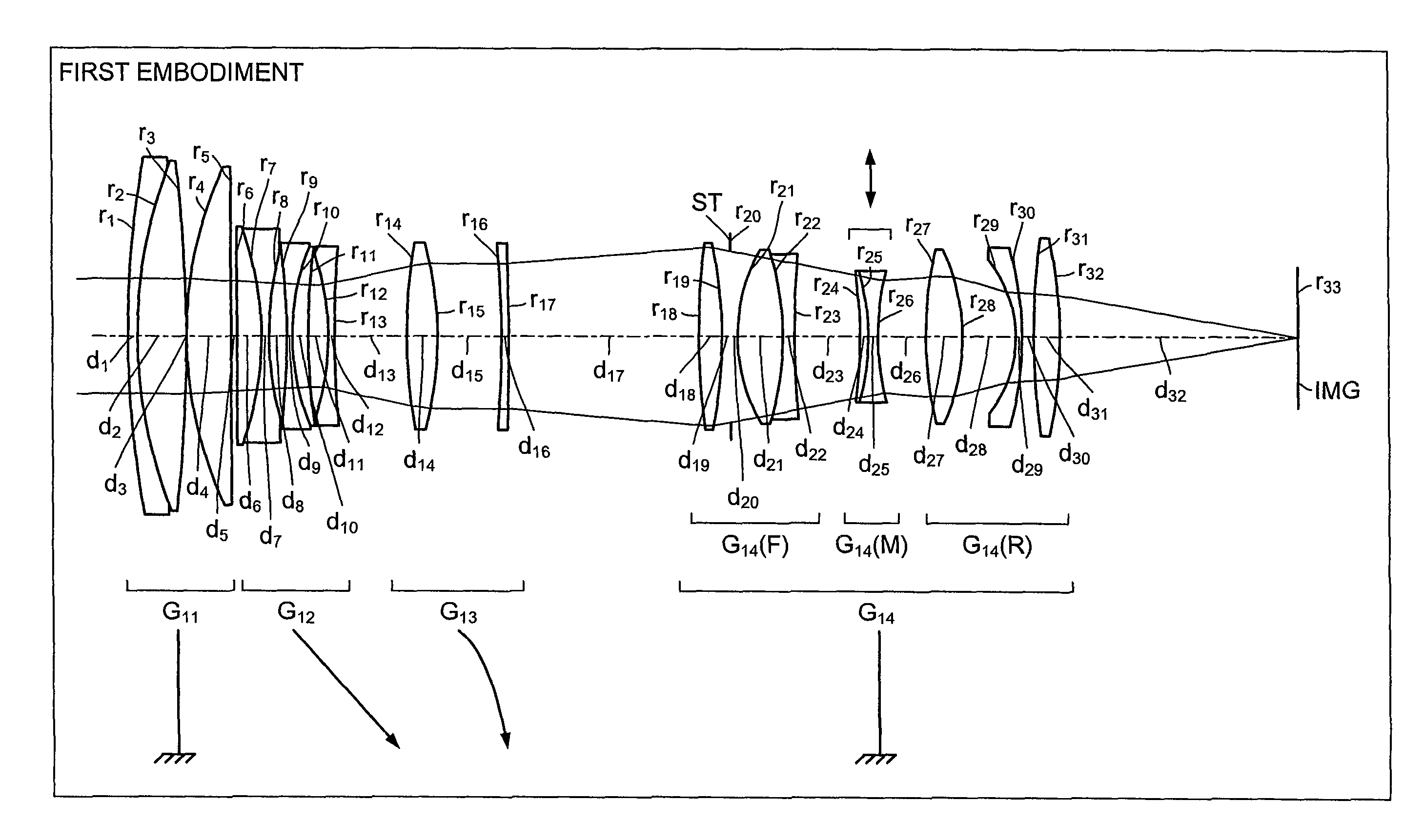
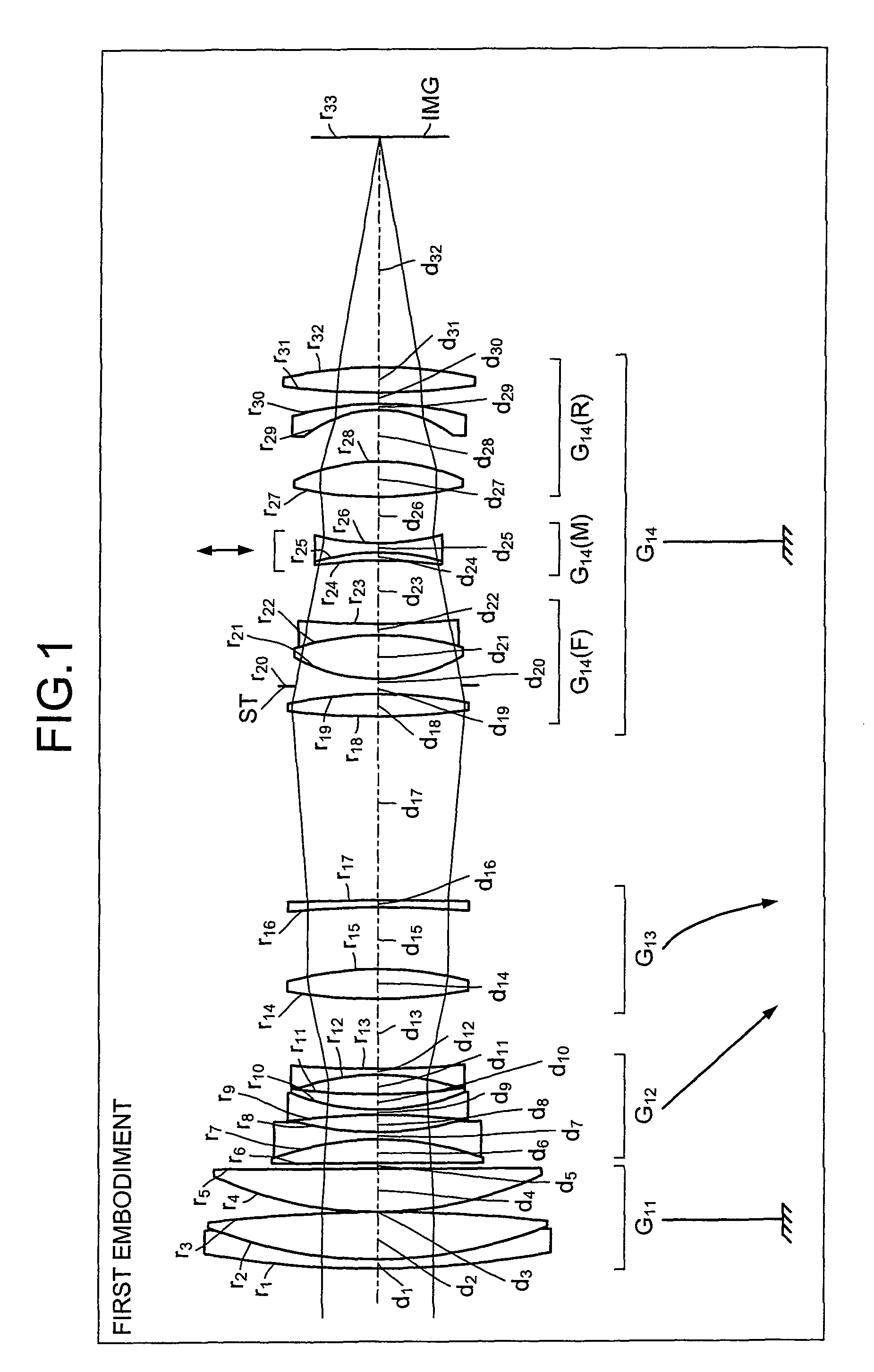
[0042]FIG. 1 depicts a cross-sectional view (along the optical axis) of the zoom lens according to a The zoom lens includes sequentially from an object side (object not depicted), a first lens group G11 having a positive refractive power, a second lens group G12 having a negative refractive power, a third lens group G13 having a positive refractive power, and a fourth lens group G14 having a positive refractive power. Further, at an imaging plane IMG, the light receiving surface of an imaging element, such as a CCD and CMOS, is disposed.

[0043]The fourth lens group G14 consists of, sequentially from the object side, a front group G14(F) having a positive refractive power, an intermediate group G14(M) configured by a cemented lens formed by a positive lens and a negative lens and having an overall refractive power that is negative, and a rear group G14(R) having a positive refractive power. In the front group G14(F), an aperture stop ST prescribing a given aperture is disposed. Furth...

second embodiment

[0066]FIG. 5 depicts a cross-sectional view (along the optical axis) of the zoom lens according to a The zoom lens includes sequentially from an object side (object not depicted), a first lens group G21 having a positive refractive power, a second lens group G22 having a negative refractive power, a third lens group G23 having a positive refractive power, and a fourth lens group G24 having a positive refractive power. Further, at the imaging plane IMG, the light receiving surface of an imaging element, such as a CCD and CMOS, is disposed.

[0067]The fourth lens group G24 consists of, sequentially from the object side, a front group G24(F) having a positive refractive power, an intermediate group G24(M) configured by a cemented lens formed by a positive lens and a negative lens and having an overall refractive power that is negative, and a rear group G24(R) having a positive refractive power. In the front group G24(F), the aperture stop ST prescribing a given aperture is disposed. Fur...

third embodiment

[0088]FIG. 9 depicts a cross-sectional view (along the optical axis) of the zoom lens according to a The zoom lens includes sequentially from an object side (object not depicted), a first lens group G31 having a positive refractive power, a second lens group G32 having a negative refractive power, a third lens group G33 having a positive refractive power, and a fourth lens group G34 having a positive refractive power. Further, at the imaging plane IMG, the light receiving surface of an imaging element, such as a CCD and CMOS, is disposed.

[0089]The fourth lens group G34 consists of, sequentially from the object side, a front group G34(F) having a positive refractive power, an intermediate group G34(M) configured by a cemented lens formed by a negative lens and a positive lens and having an overall refractive power that is negative, and a rear group G34(R) having a positive refractive power. In the front group G34(F), the aperture stop ST prescribing a given aperture is disposed. Fur...


PUM


Abstract

A zoom lens includes, sequentially from an object side, a first lens group having a positive refractive power; a second lens group having a negative refractive power; a third lens group having a positive refractive power; and a fourth lens group having a positive refractive power. Zoom is performed by moving the second and the third lens groups in a direction along an optical axis. The fourth lens group consists of, sequentially from the object side, a front group having a positive refractive power, an intermediate group configured by a cemented lens formed by a positive lens and a negative lens and having an overall refractive power that is negative, and a rear group having a positive refractive power. Blur is corrected by moving the intermediate group in a direction that is substantially orthogonal to the optical axis.

Description

BACKGROUND OF THE INVENTION[0001]1. Field of the Invention[0002]The present invention relates to a zoom lens ideal for digital still and motion cameras (DSMC), single-lens reflex cameras, and the like.[0003]2. Description of the Related Art[0004]Recently, in DSMCs and single-lens reflex cameras, zoom lenses are used in which a portion of the lenses in the first group are moved along the optical axis during focusing (see, for example, Japanese Patent Application Laid-Open Publication Nos. 2002-162564 and 2003-344766). Zoom lenses are also used in which a third or a fourth group configured by plural intermediate diameter lenses is moved along the optical axis during focusing (see, for example, Japanese Patent Application Laid-Open Publication No. 2010-44372).[0005]For example, the zoom lens recited in Japanese Patent Application Laid-Open Publication No. 2002-162564 has, sequentially from an object side, a front lens component that includes plural lenses for performing zoom and focusi...

Claims


Application Information

Patent Timeline
Patent Type & Authority Patents(United States)
IPC IPC(8): G02B27/64G02B15/14
CPCG02B15/173G02B15/14G02B27/646G02B27/64G02B15/144113
Inventor LI, DAYONG
Owner TAMRON
Why Eureka
Try Eureka