
Apparatus for joining members and assembly thereof

a technology of mechanical joints and assemblies, applied in the direction of couplings, rod connections, manufacturing tools, etc., can solve the problems of reducing the efficiency and uniformity of mechanical joints, reducing the flexibility of assembly, and reducing the assembly time and manufacturing costs. , to achieve the effect of enhancing strength and reliability, reducing assembly time and manufacturing costs

Active Publication Date: 2013-09-24
TEXTRON INNOVATIONS
View PDF27 Cites 5 Cited by
  • Summary
  • Abstract
  • Description
  • Claims
  • Application Information

AI Technical Summary

Benefits of technology

The solution provides lightweight, reliable, and flexible structural attachments with improved static and fatigue performance, reducing assembly time and costs while preventing catastrophic failures by distributing loads effectively and allowing for easy inspection of overloads.

Problems solved by technology

Failure to efficiently and uniformly transfer loads often results in a structure being subjected to stresses concentrated in localized portions of the structure.
Such concentrated, localized stresses may exceed the design criteria for the structure, even though the overall loading on the structure is within design criteria.
If the adhesive bond fails due to concentrated stresses in a particular portion of the bond, loads will no longer be efficiently transferred between the members joined by the adhesive bond.
Conventional manufacturing methods used to drill fastener holes during the detail fabrication stage often result in the holes being angularly and / or linearly mismatched when the parts are assembled.
Match-drilling is an expensive process that requires additional tooling and substantial time during the assembly stage, thus unfavorably impacting product manufacturing flow and cost.

Method used


Image

  • Apparatus for joining members and assembly thereof
  • Apparatus for joining members and assembly thereof
  • Apparatus for joining members and assembly thereof

Examples


Embodiment Construction

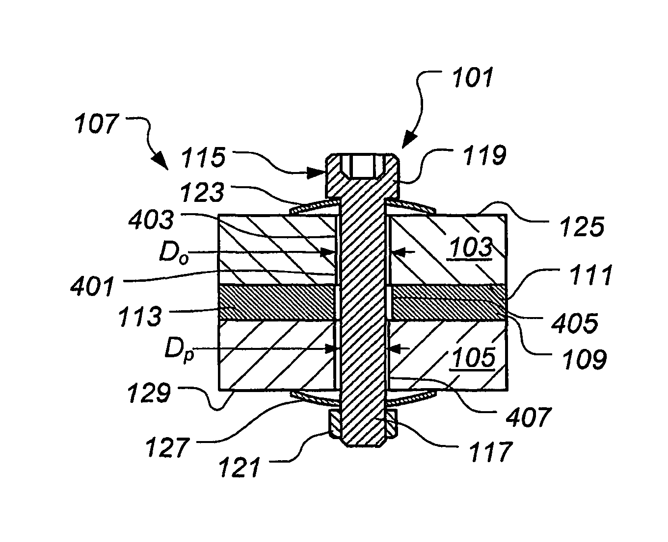
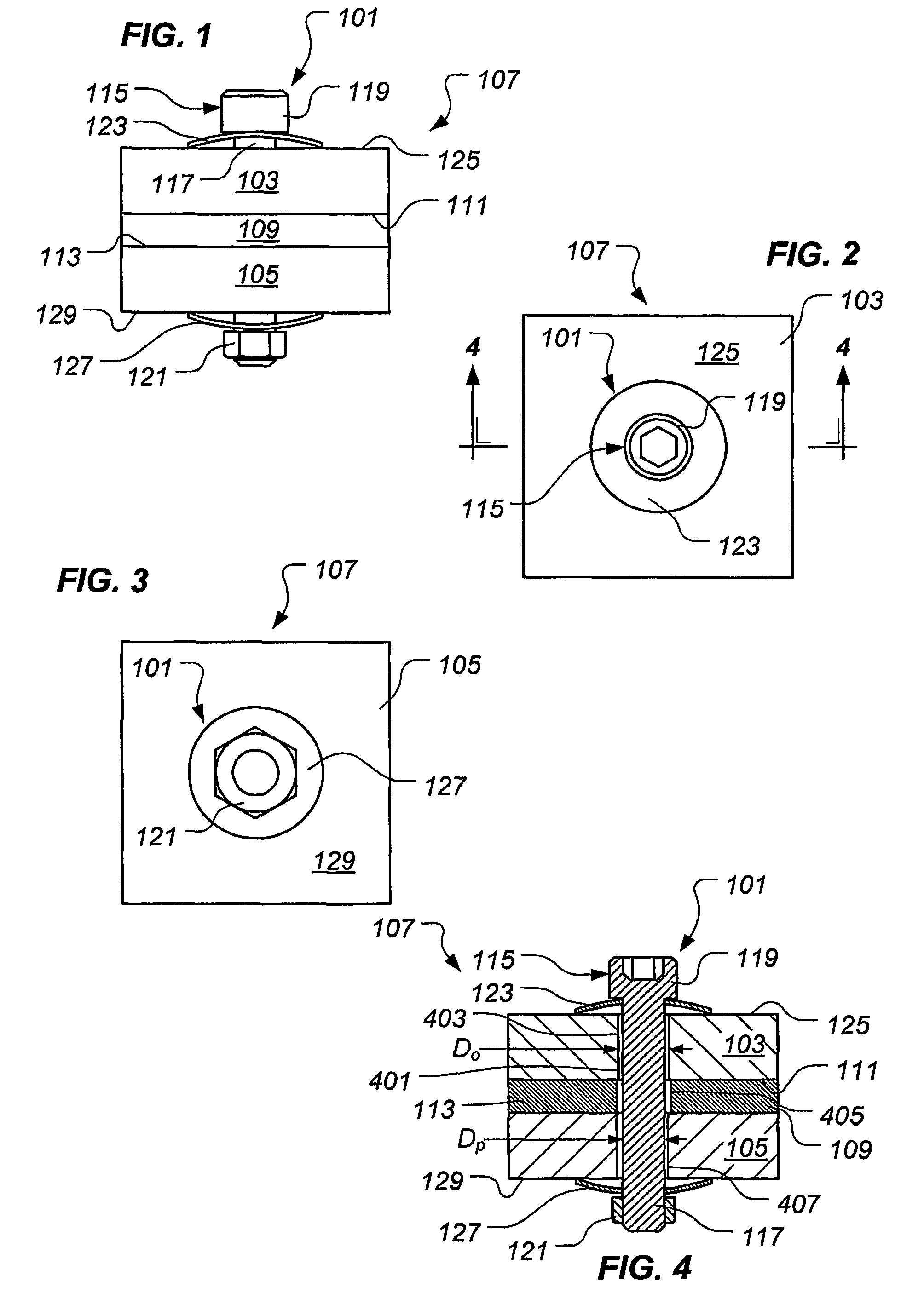
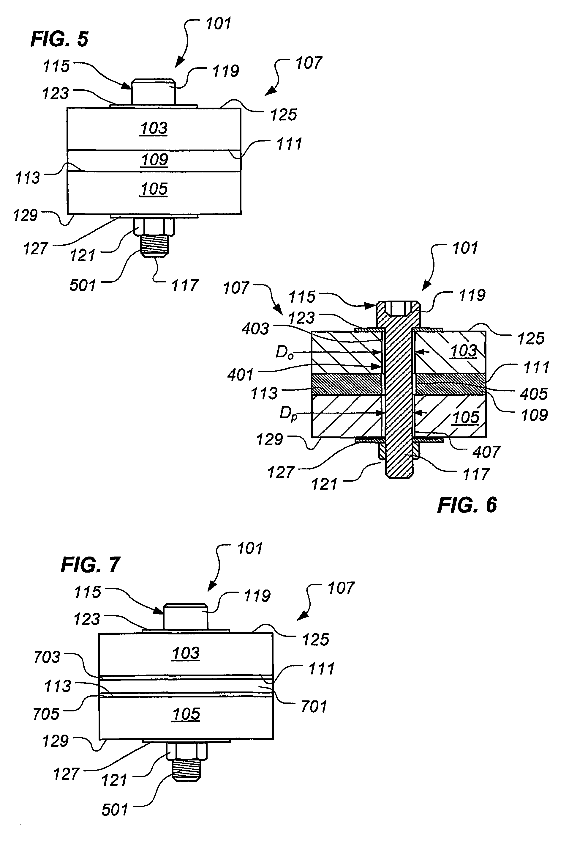
[0043]Illustrative embodiments of the invention are described below. In the interest of clarity, not all features of an actual implementation are described in this specification. It will of course be appreciated that in the development of any such actual embodiment, numerous implementation-specific decisions must be made to achieve the developer's specific goals, such as compliance with system-related and business-related constraints, which will vary from one implementation to another. Moreover, it will be appreciated that such a development effort might be complex and time-consuming but would nevertheless be a routine undertaking for those of ordinary skill in the art having the benefit of this disclosure.

[0044]In the specification, reference may be made to the spatial relationships between various components and to the spatial orientation of various aspects of components as the devices are depicted in the attached drawings. However, as will be recognized by those skilled in the ar...


PUM


Abstract

An apparatus for joining a first member and a second member includes means for joining the first member and the second member, means for transferring shear loads between the first member and the second member separate from the means for joining the first member and the second member, and means for providing a compression preload to the means for transferring shear loads between the first member and the second member. An assembly includes a first member, a second member, and means for joining the first member and the second member. The assembly further includes means for transferring shear loads between the first member and the second member separate from the means for joining the first member and the second member and means for providing a compression preload to the means for transferring shear loads between the first member and the second member.

Description

CROSS-REFERENCE TO RELATED APPLICATIONS[0001]This application claims priority to U.S. Provisional Application No. 60 / 664,577 by Hethcock et al. filed 23 Mar. 2005, entitled “Advanced Bonded Compression Joint,” which is incorporated herein by reference for all purposes.TECHNICAL FIELD[0002]The present invention relates in general to the field of mechanically-joined structural assemblies.DESCRIPTION OF THE PRIOR ART[0003]It is desirable for a structural assembly to efficiently transfer loads (e.g., shear loads) across one or more joints between components of the assembly. Furthermore, in many structures it is preferred that the loads be substantially uniformly transferred through the entire structure. Failure to efficiently and uniformly transfer loads often results in a structure being subjected to stresses concentrated in localized portions of the structure. Such concentrated, localized stresses may exceed the design criteria for the structure, even though the overall loading on the...

Claims


Application Information

Patent Timeline
Patent Type & Authority Patents(United States)
IPC IPC(8): F16B11/00
CPCF16B5/0266F16B11/006Y10T403/32991Y10T403/47Y10T403/45B25B31/00F16B7/10
Inventor HETHCOCK, JAMES D.JONES, RODNEY H.MAY, CARL A.
Owner TEXTRON INNOVATIONS
Learn More