Elongate battery for implantable medical device

a medical device and battery technology, applied in the field of implantable medical devices, can solve the problem of relative high energy capacity to prolong the useful life of the device, and achieve the effect of sufficient operating li

Active Publication Date: 2013-09-24
MEDTRONIC INC
View PDF31 Cites 316 Cited by
  • Summary
  • Abstract
  • Description
  • Claims
  • Application Information

AI Technical Summary

Problems solved by technology

Also, the generator can have a relatively high energy capacity to prolong the useful life of the device.

Method used


Image

  • Elongate battery for implantable medical device
  • Elongate battery for implantable medical device
  • Elongate battery for implantable medical device

Examples


Embodiment Construction

[0033]Exemplary embodiments will now be described more fully with reference to the accompanying drawings.

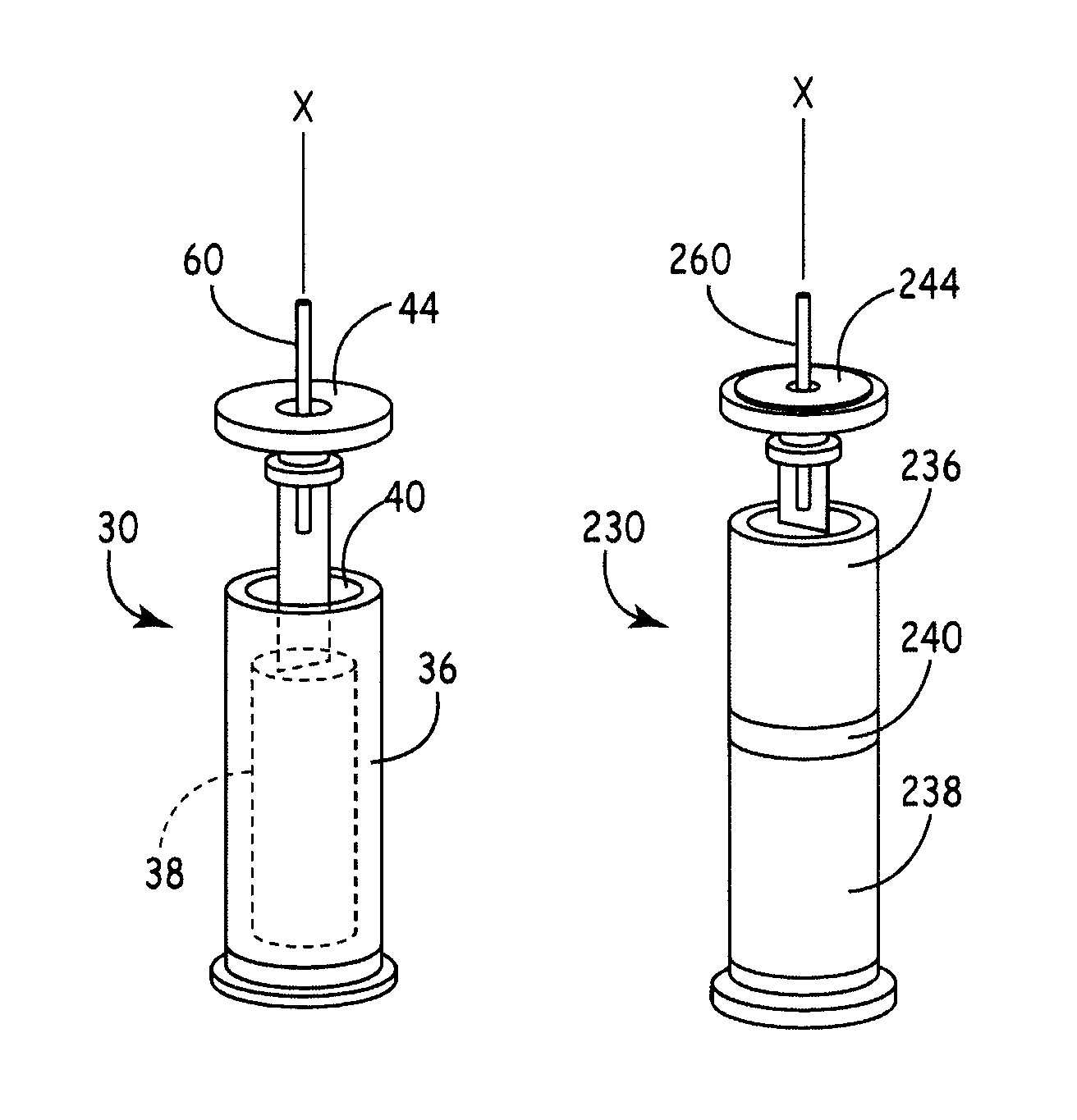
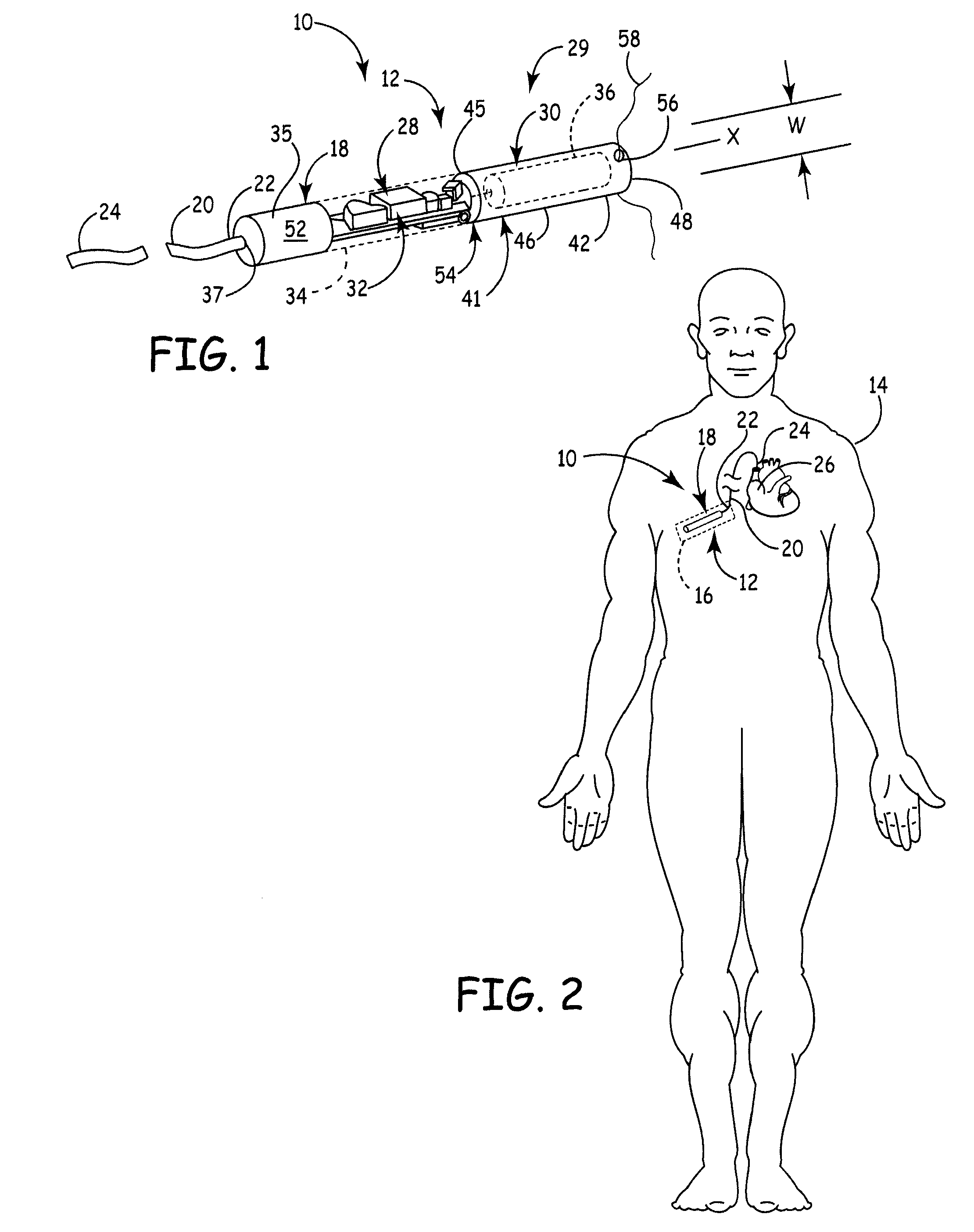
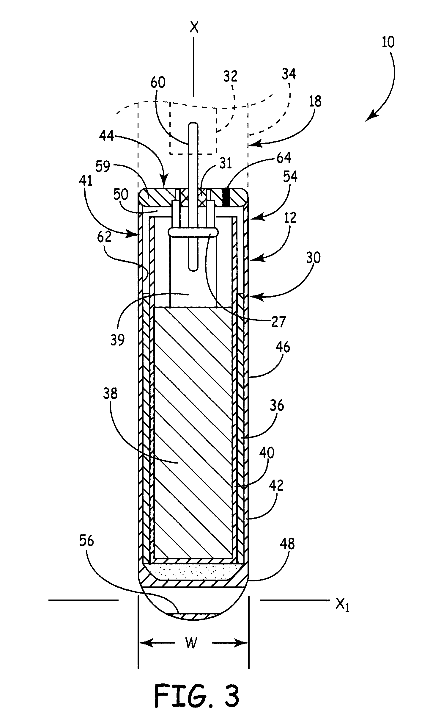
[0034]Referring initially to FIGS. 1, 2, and 3, an implantable medical device 10 (IMD) is illustrated according to various teachings of the present disclosure. The medical device 10 can be of any suitable type, and in some embodiments, the medical device 10 can be a cardiac pacemaker device 12 (i.e., an implantable pulse generator). The cardiac pacemaker device 12 can be an electronic device for providing an electrical cardiac signal to stimulate cardiac tissue and to thereby maintain a predetermined heart beat as described in greater detail below. It will be appreciated, however, that the medical device 10 can be of any other suitable type, such as an implantable cardioverter-defibrillator (ICD), without departing from the scope of the present disclosure. In other embodiments, the medical device 10 can be a neural device for providing electrical signals to a nerve or for any oth...


PUM

PropertyMeasurementUnit
volumeaaaaaaaaaa
impedanceaaaaaaaaaa
volumeaaaaaaaaaa

Abstract

A battery assembly for a medical device includes an elongate cathode, an elongate anode, an electrolyte, and an elongate housing assembly encapsulating the cathode, the anode, and the electrolyte. The battery assembly also includes a first electrode that is exposed from and electrically insulated from the housing assembly. One of the anode and the cathode is electrically coupled to the first electrode, and the other of the anode and the cathode is electrically coupled to the housing assembly. One of the cathode and the anode includes a first portion and a second portion disposed in spaced relationship from the first portion. The other of the cathode and the anode is disposed between the first and second portions.

Description

CROSS-REFERENCE TO RELATED APPLICATIONS[0001]This application claims the benefit of U.S. Provisional Application No. 61 / 182,337, filed on May 29, 2009. The entire disclosure of the above application is incorporated herein by reference.FIELD[0002]The present disclosure relates to an implantable medical device, such as a cardiac pacemaker device, and in particular, an implantable medical device with an elongate battery.INTRODUCTION[0003]Several medical devices have been designed to be implanted within the human body. Implantable medical devices (IMDs), such as implantable pulse generators (IPGs), often include an elongate, flexible lead having one end operatively coupled to cardiac tissue and an opposite end operatively coupled to a generator (e.g., a pulse generator). The generator can include a power source, a sensing amplifier which processes electrical manifestations of naturally occurring heart beats as sensed by the lead, computer logic, and output circuitry, which delivers the ...

Claims


Application Information

Patent Timeline
Patent Type & Authority Patents(United States)
IPC IPC(8): H01M2/02H01M2/26H01M6/08H01M2/28H01M50/147H01M50/179H01M50/541H01M50/627
CPCH01M2/0232H01M2/0404H01M6/14H01M2/361H01M6/02H01M2/06A61N1/378H01M50/174H01M50/147H01M50/627H01M50/179
Inventor LUND, JEFFREY S.MAY, STEVEN J.MERRITT, DONALD R.ZHAO, HAILIANG
Owner MEDTRONIC INC
Why Eureka
Try Eureka