
Lock pin for variable valve timing mechanism

a variable valve timing and lock pin technology, applied in the direction of valve details, valve arrangements, machines/engines, etc., can solve the problems of affecting the perception of engine quality, reducing customer satisfaction, and affecting the quality of the engine, so as to achieve reliable engagement and disengagement of the lock pin

Inactive Publication Date: 2013-10-01
TOYOTA MOTOR CO LTD
View PDF9 Cites 1 Cited by
  • Summary
  • Abstract
  • Description
  • Claims
  • Application Information

AI Technical Summary

Benefits of technology

The present invention introduces a variable valve timing mechanism with a lock pin that solves previous issues with lock pins, resulting in reliable engagement and disengagement.

Problems solved by technology

However, if the lock pin fails to properly engaged or disengage, the variable valve timing mechanism produces increased noise and vibrations during shutdown and startup procedures.
The increase in noise and vibrations result in a decrease in customer satisfaction and affects the perception of quality of the engine.
However, the linear outer side profile provides unreliable engagement of the lock pin 110 within the lock bore 112.
However, due to the linear outer side profile of the tapered cylindrical shape of the insertion section 210 the lock pin 200 is susceptible to sticking and jamming during disengagement.
The resulting jam between the insertion section 210 and the lock bore 212 resulted in increased noise and vibrations of the variable valve timing mechanism.

Method used


Image

  • Lock pin for variable valve timing mechanism
  • Lock pin for variable valve timing mechanism
  • Lock pin for variable valve timing mechanism

Examples


Embodiment Construction

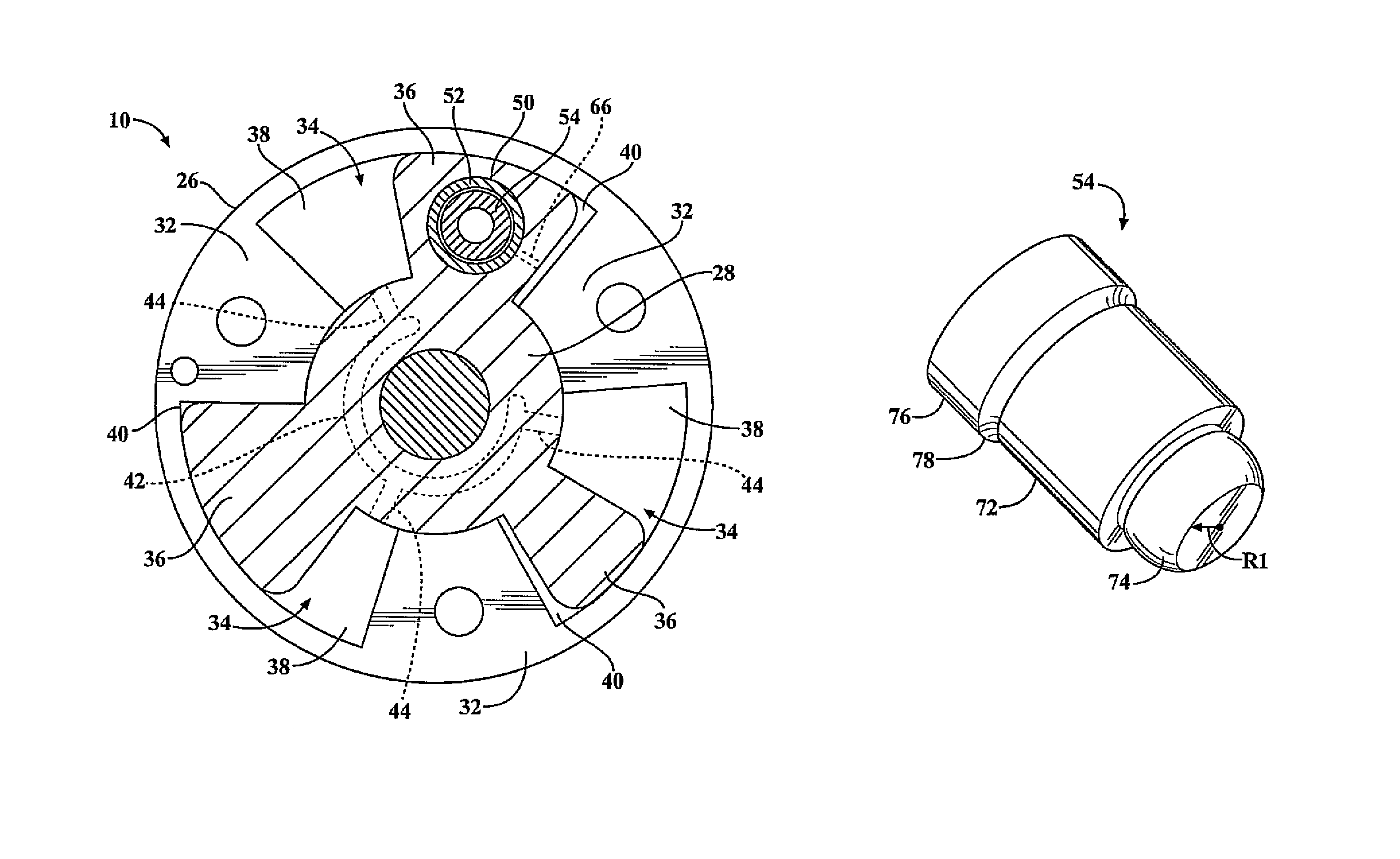
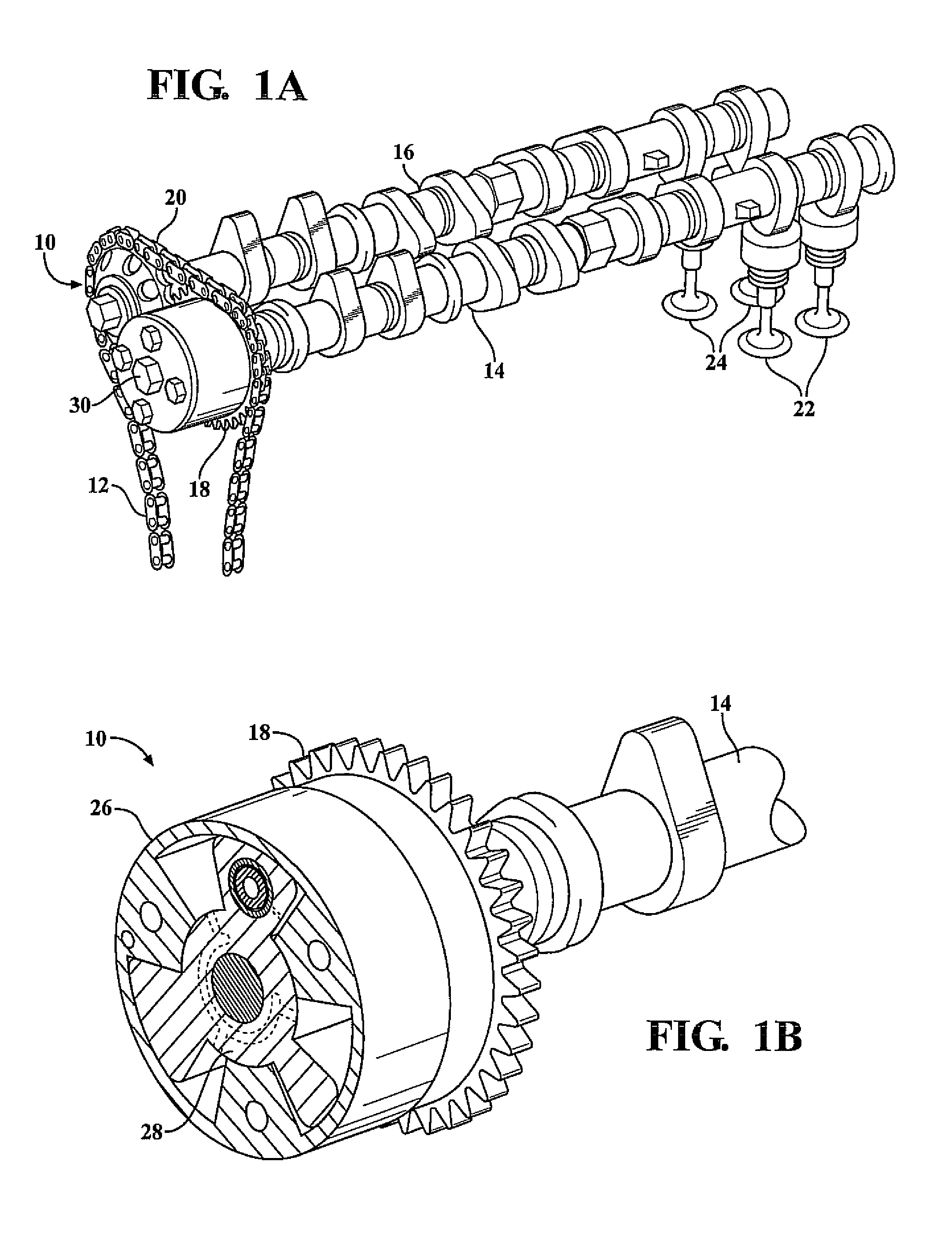
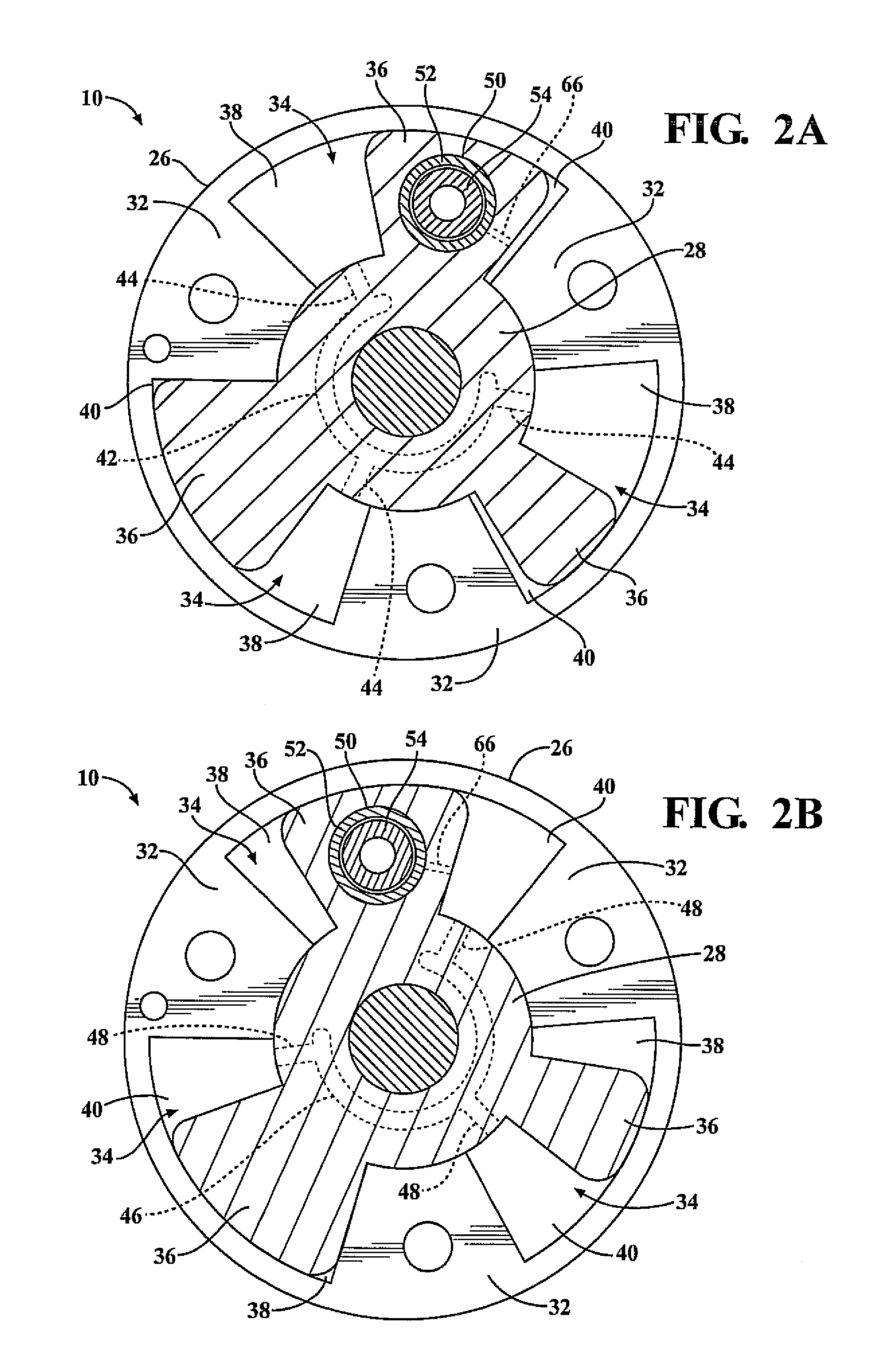
[0025]The present invention has utility as a variable valve timing mechanism, for an internal combustion engine, that provides a lock pin that reliably engages and disengages with a lock bore to prohibit or allow relative rotation between a rotor and housing. By providing the lock pin with an insertion section having a segmented spherical shape, the lock pin can be easily inserted within a lock bore due to the smaller diameter the distal end of the insertion section with respect to the lock bore, and easily disengaged from the lock bore while avoiding a jamming effect between the lock pin and the lock bore due to the nonlinear.

[0026]With reference to FIG. 1, a variable valve timing mechanism for an internal combustion engine is generally illustrated at 10. The engine includes a crankshaft in which the reciprocating motion of pistons of the engine is converted into a rotary motion of the crankshaft. A timing chain 12 transmits the driving force from the crankshaft to an intake side c...


PUM


Abstract

The variable valve timing mechanism includes a housing, a rotor rotatably supported within the housing, and a lock pin. The housing includes a plurality of fluid chambers one of which includes a lock bore. The rotor includes a central portion and a plurality of vanes extending radially from the central portion. Each of the vanes extends into the fluid chambers of the housing to define an advanced fluid chamber and a retarded fluid chamber. One of the plurality of vanes includes a pin bore. The lock pin includes a shank section and an insertion section. The insertion section includes a nonlinear outer side profile. The lock pin is slidably received within the pin bore between an unlocked position and a locked position in which the insertion section of the lock pin is received within the lock bore of the housing thereby prohibiting relative rotation between the housing and the rotor.

Description

FIELD OF THE INVENTION[0001]The present invention is directed to a variable valve timing mechanism. More particularly, a variable valve timing mechanism having a lock pin that includes an insertion section having a segmented spherical shape.BACKGROUND OF THE INVENTION[0002]Most modern automotive vehicles include a variable valve timing mechanism in order to vary the opening and closing valve times of the exhaust and intake valves. Typically variable valve timing mechanisms include a lock pin that locks the variable valve timing mechanism during a shutdown of the internal combustion engine in preparation for the engine's next start. However, if the lock pin fails to properly engaged or disengage, the variable valve timing mechanism produces increased noise and vibrations during shutdown and startup procedures. The increase in noise and vibrations result in a decrease in customer satisfaction and affects the perception of quality of the engine.[0003]With reference to FIGS. 5A-5C, a pr...

Claims


Application Information

Patent Timeline
Patent Type & Authority Patents(United States)
IPC IPC(8): F01L1/34
CPCF01L1/3442F01L2001/0537F01L2001/34456F01L2001/34469F01L2103/01F01L2250/02F01L2820/041F01L2303/01
Inventor LIN, YEONGCHINGBERNER, NEALBERNIER, KYLENOGUCHI, TOSHIHARU
Owner TOYOTA MOTOR CO LTD
Learn More