Transfer case with clutch actuator

a technology of clutch actuator and transfer case, which is applied in the direction of mechanically actuated clutches, transportation and packaging, gearing, etc., can solve the problems of complicated control system and high cost, and achieve the effect of reliable engagement and disengagement of four-wheel drive mod

Active Publication Date: 2012-04-17
WIA CORP
View PDF21 Cites 20 Cited by
  • Summary
  • Abstract
  • Description
  • Claims
  • Application Information

AI Technical Summary

Benefits of technology

[0007]In order to solve the above described drawbacks and other problems of the conventional transfer case to be recognized by following disclosure, the present invention provides a new and useful transfer case and its actuating system for applying force to a clutch, which enables reliable engagement and disengagement of the four-wheel drive mode without malfunctions. The mode shift can be made by selection of the operator or otherwise automatically engaged on demand in order to drive and release the secondary wheels.
[0008]The present invention also provides a useful transfer case and its actuating system which utilizes an electric actuator, such as an electrically actuated or controlled motor, to actuate the clutch. The electric motor of the system can be provided with relatively low cost in comparison to the conventionally-used hydraulic actuators which also make the control system more complicated and expensive. In addition, the electric motor of the invention, typically for the manual selection system, can be selected from the same or similar low cost actuator motors currently used for the conventional synchronizer. Also, because the actuator system of the invention uses a power increasing mechanism such as a rotary cam and a pivoting lever mechanism, the drive torque of the electric motor is multiplied to effectively actuate the clutch with a relatively low torque motor.
[0011]In one preferred embodiment, the clutch actuator means is a pivot lever pivotally moveable in association with rotation the actuator shaft coupled with the actuator for said applying the axial force to the frictional clutch plates. In another preferred embodiment, the clutch actuator means is a sliding lever moveable in an axial direction of the actuator shaft in association with rotation the actuator shaft coupled with the actuator. The transfer case preferably comprises a chain for rotating the outer drum member in association with said rotation of the first output shaft. According to the present invention, the torque of the electric motor is effectively magnified by the rotary cam and the lever mechanism (e.g., the pivot lever) to effectively apply suitable axial force to the clutch. The force magnifying rate can be varied depending on the design and configuration of the rotary cam and the pivot lever and to meet the requirement of the particular four wheel drive system of the vehicle. The force may be further magnified by another lever (e.g., a clutch lever) disposed in the clutch with a thrust bearing interposed between this lever and the pivot lever of the actuator.

Problems solved by technology

The electric motor of the system can be provided with relatively low cost in comparison to the conventionally-used hydraulic actuators which also make the control system more complicated and expensive.

Method used


Image

  • Transfer case with clutch actuator
  • Transfer case with clutch actuator
  • Transfer case with clutch actuator

Examples


Embodiment Construction

[0019]Preferred embodiments of the present invention are described herein with reference to the drawings. The power transfer system and its actuator system of the invention may be applied for a manual selection type or also for an automatic on-demand system.

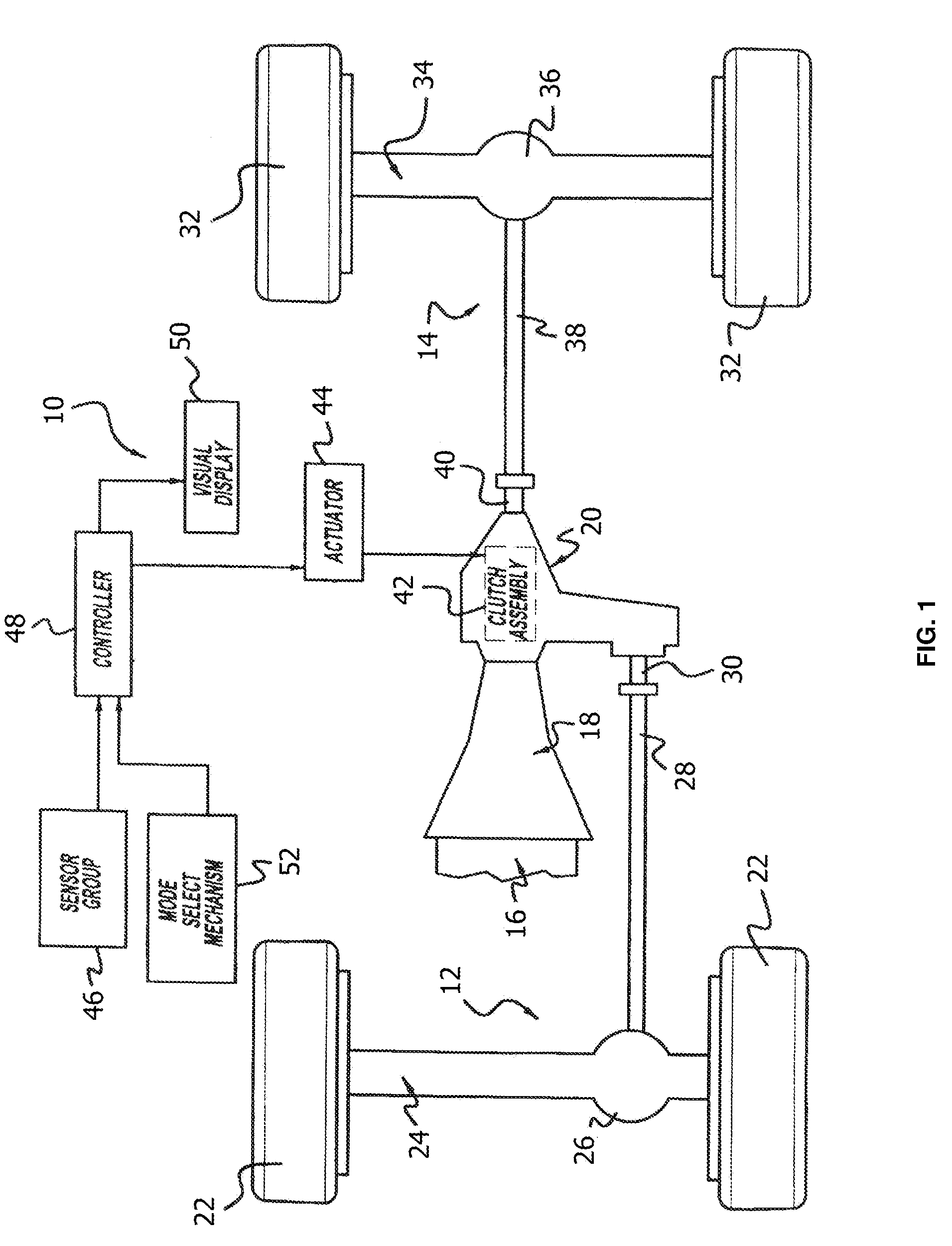
[0020]Referring to FIG. 1 of the drawings, a drivetrain for a four-wheel drive vehicle is schematically shown, which is interactively associated with a power transfer system 10 of the present invention. The vehicle drivetrain includes a front driveline 12 (typically a secondary driveline) and a rear driveline 14 (typically a primary driveline) both drivable from a source of power, such as an engine 16, through a transmission 18 which may be of either the manual or automatic type.

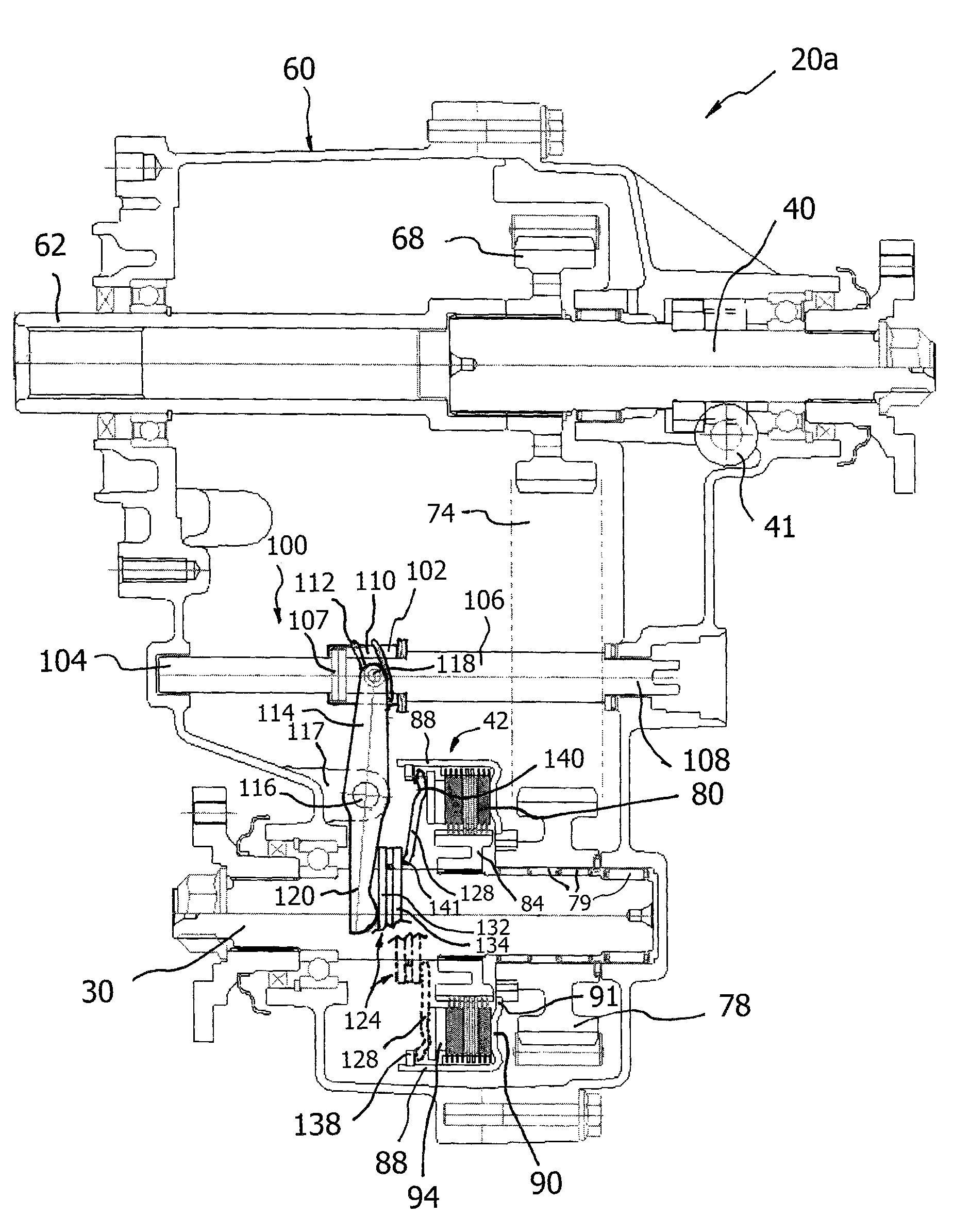
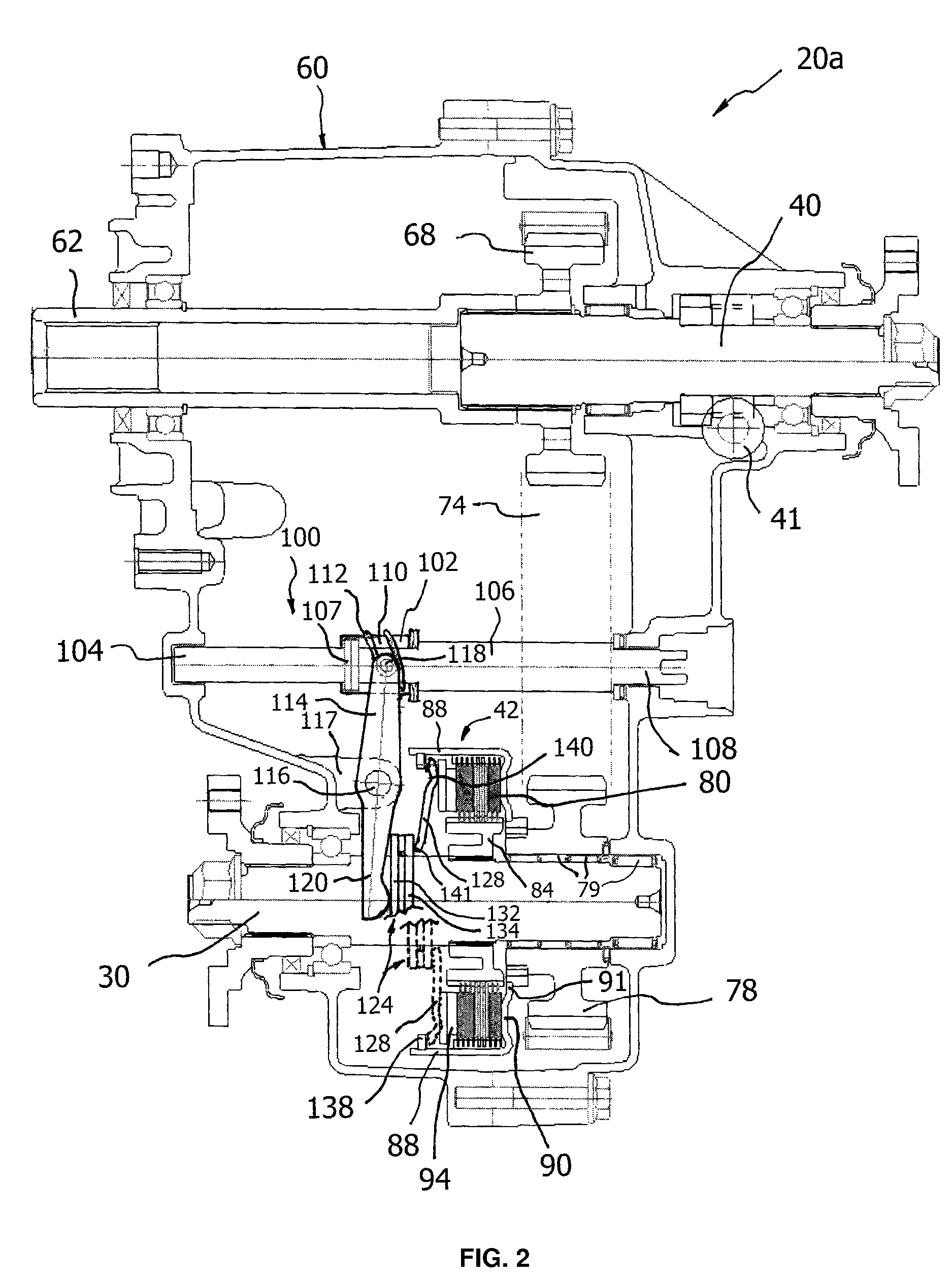
[0021]In the exemplary embodiment shown, the drivetrain includes a transfer case 20 for transmitting drive torque from engine 16 and transmission 18 to front driveline 12 and rear driveline 14. Front driveline 12 includes a pair of front wheels 22 connect...


PUM


Abstract

A transfer case for selectively coupling a secondary driveline with a primary driveline comprises: a first output shaft; a second output shaft; a clutch assembly disposed at the second output shaft, the clutch assembly including inner and outer drum members, one of the inner and outer drum members rotatable in association with rotation of the first output shaft and the other one of the inner and outer drum members coupled with the second output shaft, the clutch assembly further including a plurality of frictional clutch plates, the frictional clutch plates formed of at least one frictional clutch plate coupled with the inner drum member and at least one frictional clutch plate coupled with the outer drum member; an actuator shaft rotatably coupled with an actuator; and a clutch actuator means coupled with the actuator for applying axial force to the frictional clutch plates to transmit a drive torque of the first output shaft to the second output shaft. The clutch actuator means can be a pivot lever pivotally moveable in association with rotation the actuator shaft coupled with the actuator for said applying the axial force to the frictional clutch plates, or can be a sliding lever moveable in an axial direction of the actuator shaft in association with rotation the actuator shaft coupled with the actuator.

Description

FIELD OF THE INVENTION[0001]The present invention relates to a power transfer system, and more particularly, to a transfer case for four-wheel drive vehicles, the transfer case having an electric actuator for applying forces to a clutch mechanism in order to couple the secondary driveline to the primary driveline of the vehicle.BACKGROUND OF THE INVENTION[0002]Many modern vehicles, in particular sport utility vehicles and light trucks, are equipped with a four-wheel drive system to improve traction, which comprises a transfer case for interconnecting and also distributing power between the primary and secondary drivelines to cause the vehicle to drive in a four-wheel drive condition. Such four-wheel drive vehicles are equipped with a transfer case, which receives drive torque from the transmission of the vehicle and connects or distributes the power between the primary driveline for driving a first set of wheels (for example, the rear wheels) and the secondary driveline for driving ...

Claims


Application Information

Patent Timeline
Patent Type & Authority Patents(United States)
IPC IPC(8): B60K23/08
CPCF16D23/12B60K17/344F16D27/115F16D28/00F16D2023/123Y10T74/19074Y10T74/19251
Inventor BOWEN, THOMAS C.
Owner WIA CORP
Why Eureka
Try Eureka