
Ultrasonic humidifier

a humidifier and ultrasonic technology, applied in the field of ultrasonic humidifiers, can solve the problems of “white dust” and the effect of the method, and the sale of these humidifiers has almost died, and the discharging of vapors in the whole room cannot be achieved

Active Publication Date: 2013-10-01
VORNADO AIR LLC
View PDF12 Cites 61 Cited by
  • Summary
  • Abstract
  • Description
  • Claims
  • Application Information

AI Technical Summary

Problems solved by technology

After several years on the market the problems of the ultrasonic humidifiers became known to the public, and the sales of these humidifiers all but died.
The major problem was “White Dust”.
This method is effective but does not allow for any whole-room disbursement of the vapors.

Method used


Image

  • Ultrasonic humidifier
  • Ultrasonic humidifier

Examples


Embodiment Construction

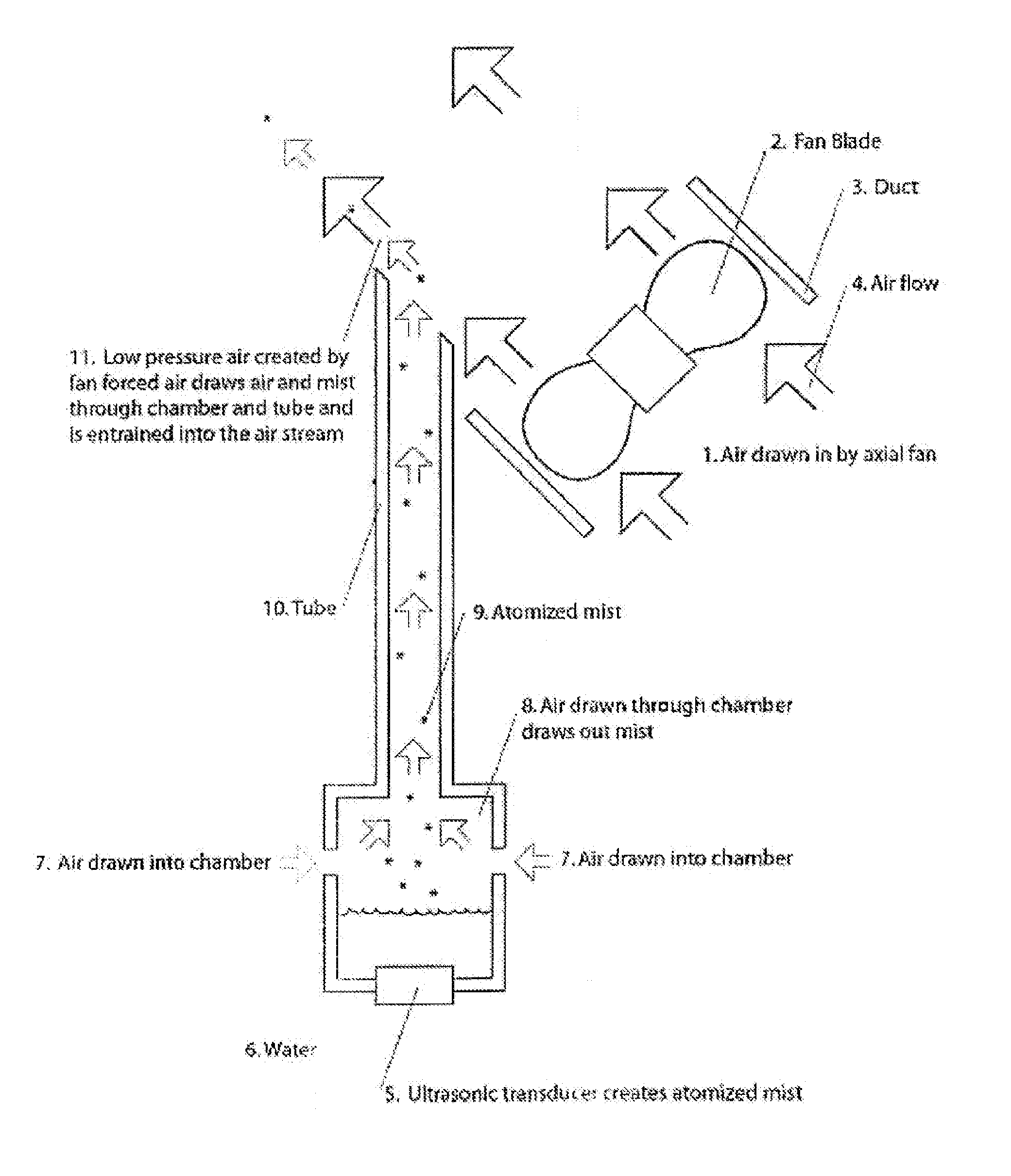
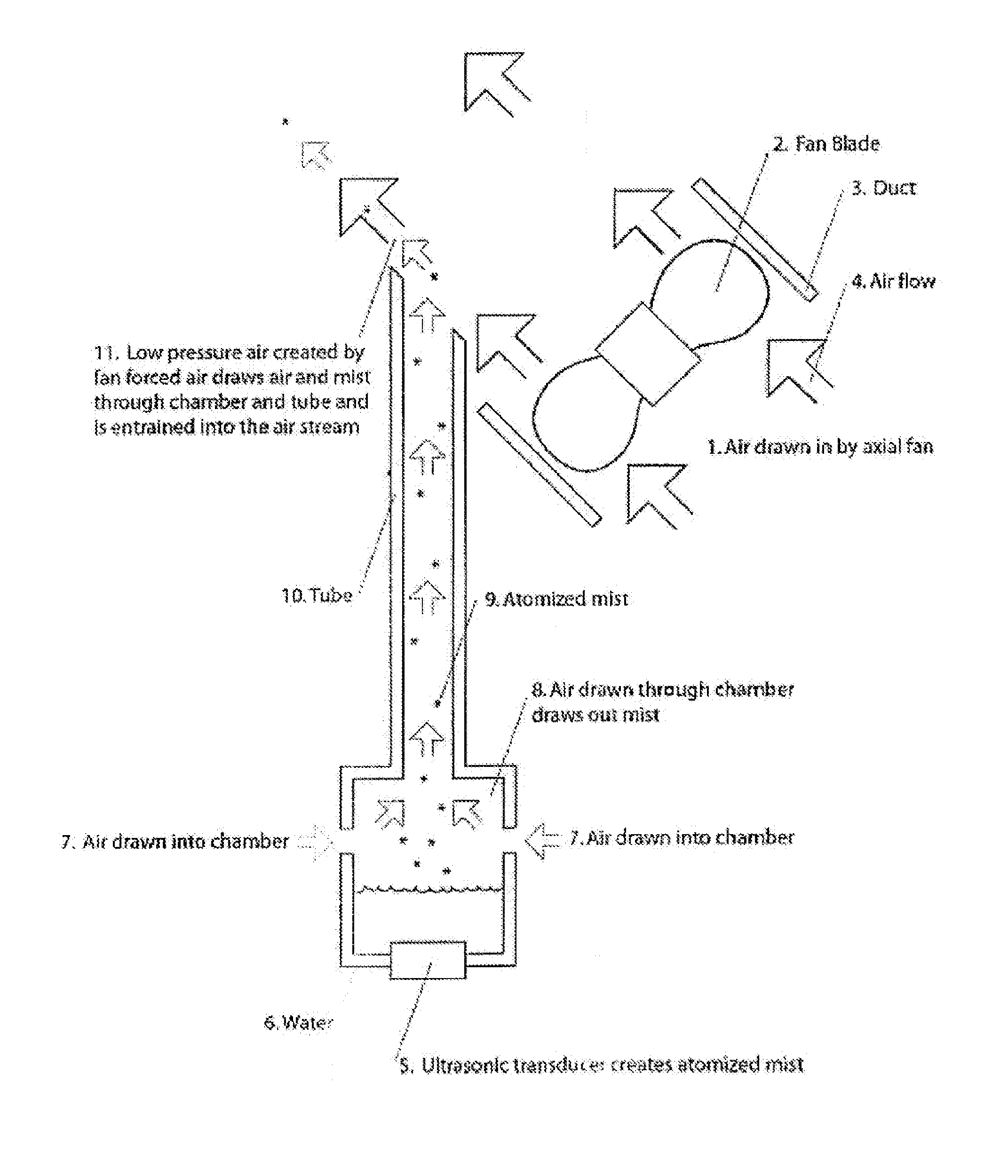
[0012]Referring to FIG. 1, air is drawn into a fan duct and propelled by a fan. The propelled air stream is passed over a tube positioned above a water chamber. The water chamber may include an inlet for water from a reservoir that is configured to keep the water level in the chamber relatively constant. An ultrasonic transducer may be positioned at the bottom of the chamber and is configured to produce an atomized mist in the area of the chamber above the surface of the water. One or more inlets may be positioned above the water surface to allow air to be drawn into the chamber and up through the tube.

[0013]As the propelled air passes over the opening of the tube, the relatively low pressure of the propelled air results in a negative pressure at the top of the tube. The air and atomized mist in the tube in turn migrates into the fan duct and is entrained with the propelled air. Air is drawn into the chamber at the bottom of the tube through the inlets.

[0014]This allows for the addi...


PUM

PropertyMeasurementUnit
angleaaaaaaaaaa
mechanical energyaaaaaaaaaa
ultrasonic energyaaaaaaaaaa

Abstract

An ultrasonic humidifier is disclosed including a chamber, an ultrasonic transducer positioned at the bottom of the chamber, a passage in fluid communication with the chamber, a duct having an inlet and an outlet, the duct being in fluid communication with the passage by way of a passage outlet, a fan positioned in the duct and disposed between the duct inlet and the passage outlet. The fan is configured to propel air through the duct and over the passage outlet such that vapors in the chamber may be drawn into the duct.

Description

CROSS REFERENCE TO RELATED APPLICATION[0001]This application is a U.S. National Application of International Application PCT Application No. PCT / US2009 / 037123 filed on Mar. 13, 2009, which claims the benefit of priority from U.S. Provisional Patent Application No. 61 / 036,238 filed Mar. 13, 2008. The disclosures of International Applicant PCT Applicant No. PCT / US2009 / 037123 and U.S. Provisional Patent Application No. 61 / 036,238 are incorporated herein by reference.BACKGROUND[0002]There are four major types of mechanical humidifiers. Steam humidifiers boil water and release the warm steam into a room. Impeller humidifiers utilize a fast rotating disk in combination with a comb to first liberate large droplets of water and then break the droplets into smaller diffusible droplets that are introduced into the room. Evaporative systems use a wick that in positioned in a water source. The water migrated along the wick by capillary action and evaporates into the air. A blower may be used to...

Claims


Application Information

Patent Timeline
Patent Type & Authority Patents(United States)
IPC IPC(8): B01F3/04
CPCF24F6/12F24F2006/125Y02B30/80B05B7/0075B05B17/0615Y02B30/70
Inventor EDIGER, GLEN W.ISRAEL, GARY P.
Owner VORNADO AIR LLC
Learn More