Reduced pressure differential hydroelectric turbine system

a hydroelectric turbine and differential hydroelectric technology, applied in the direction of electric generator control, renewable energy generation, greenhouse gas reduction, etc., can solve the problems of sacrificing downstream pressure, increasing flow velocity or speed, and turning the generator faster

Inactive Publication Date: 2013-10-01
ALVAREZ RAYMOND +1
View PDF23 Cites 1 Cited by
  • Summary
  • Abstract
  • Description
  • Claims
  • Application Information

AI Technical Summary

Benefits of technology

[0015]Since the system produces low voltage and powers devices that are already designed to operate with low voltage, expensive electricians are not required for installation or maintenance. Additionally, there will be less liability exposure to landowners and contractors working with or maintaining the system since low voltage supply and equipment are generally viewed as being extremely safe.
[0023]Bringing the flow back to the center and on itself, as the Francis does, reduces flow velocity and contributes to restriction and would be inefficient relative to the invention's stated design objective.
[0026]Turns in pipe direction leading into and out of the inlet and outlet sections of the inventions turbine ideally follow the same or similar sweeping curved designs contained within the turbine for the purpose of minimizing hydraulic restriction and pressure loss. Swept pipe sections or flexible hose can be utilized and can be made of a variety of materials including rubbers, poly materials, plastic materials, composites, iron, steel, alloys or any other material.
[0027]A by-pass valve can be any type of manual or automatic valve that can be adjusted to open or close, or any position in between. A manual valve such as a gate or ball valve could be adjusted and set at a variety of positions to enable more or less performance by the turbine. An automatic valve such as a solenoid hydraulic valve is utilized to restrict pipe line flow by setting the opening height of its internal flow control mechanism or by completely closing the device when full turbine performance is needed. A by-pass control valve option can also include actuation type valves or valves that are incrementally adjusted by a servo motor or an actuator. Such valve systems can be used to more precisely control the amount of flow that alternatively passes through the by-pass or through the main pipe line. Multiple by-pass lines can be incorporated to further contribute to more precise flow and pressure regulation.

Problems solved by technology

Such restriction increases flow velocity or speed across the impeller's veins or blades and turns the generator faster to produce more power, but subsequently sacrifices downstream pressure in the process.
However, there are numerous other uses or applications that would benefit substantially from hydroelectric turbine power if it could be utilized, but can not at this time because of the restrictive nature or pressure differential characteristics.
Such systems are usually supplied by metered utility power, wind or solar power which can be difficult to impossible or impractical to implement.
From an aesthetic stand point they are not attractive for urban and suburban use and can be susceptible to vandalism because of the high profile installation requirements of both systems.
Furthermore, in remote locations like rural environments, they are even more susceptible to theft and vandalism, again because of their high profile nature necessary to produce power.
Solar and wind generating systems can be very expensive to purchase and do not guaranty a regular supply of energy.
They are dependant upon favorable weather conditions, which can present enormous problems to mission critical systems that might depend on them for power.

Method used


Image

  • Reduced pressure differential hydroelectric turbine system
  • Reduced pressure differential hydroelectric turbine system
  • Reduced pressure differential hydroelectric turbine system

Examples


Embodiment Construction

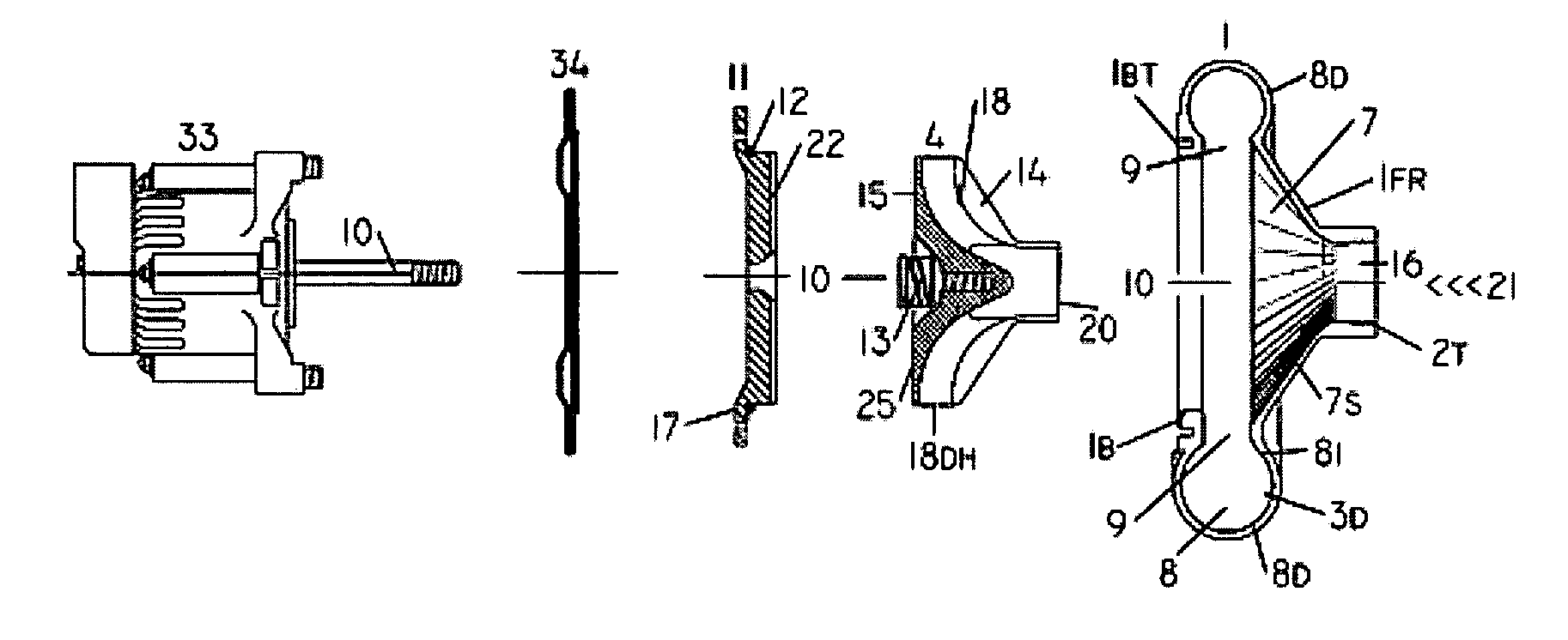
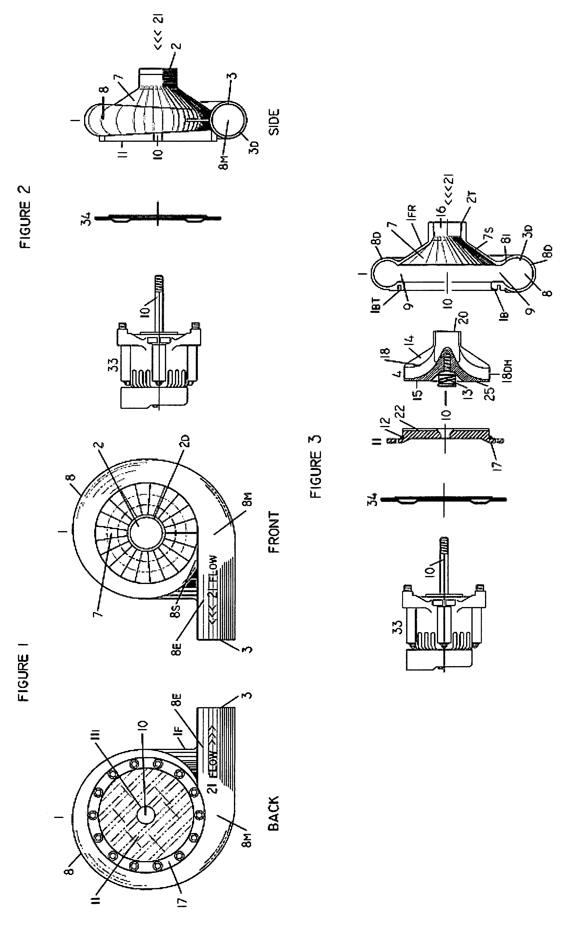
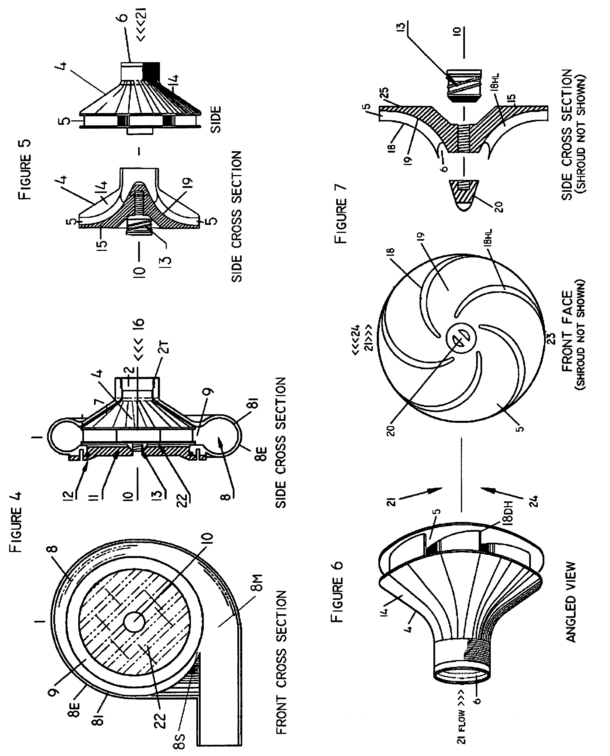
[0013]The hydroelectric turbine generator system of this invention is called a small, mini, micro or pico type reaction turbine design and is capable of maintaining an amount equal to or less than fifty 50 percent of the dynamic pressure differential between said inlet and outlet sections.

[0014]Most small and large scale water or fluid flow delivery or transfer systems require certain amounts of hydraulic pressure to drive them or to push fluid from one location to another through a pipe system or pipe line network. Utilizing the kinetic energy from fluid flow under hydraulic pressure to power electronic systems or other electrical devices in remote areas is a logical way to promote the use of such important electronic monitoring, management and control systems. Remote facilities like fixed cellular sites, wireless repeater stations, weather or atmospheric sensors or even homes and commercial or industrial facilities could be powered if a pipe line that contains a fluid flowing unde...


PUM


Abstract

This invention involves a hydroelectric turbine system that is capable of producing electricity while sustaining a majority of the fluid flow or hydraulic pressure within the pipe line or pipe network driving the system. The system's objective is to shave as little pressure as possible from an enclosed pipe system that requires pressure to operate and function properly. More particularly, this invention relates to a hydroelectric turbine generator system wherein the system is specially designed and configured with an unique impeller and fluted turbine housing that enable a generator device to produce a particular amount of electric current and voltage, while yet minimizing flow restriction and pressure loss to the fluid pressure driving the system. Application of this technology includes all fluid flow or fluid transfer systems that require sustained pressure to move fluids like water or other materials from one location or point to another, through pipes, pipe systems or networks, regardless of distance or pipe size diameters. This invention, for example will be ideally suited for powering electronic control or monitoring systems in landscapes, parks, roadway easements, golf courses or public water transfer systems or other remote sites that may require power. Utilization of this invention provides an ecological and reliable energy production source, usually on a small scale, in remote locations where incorporating other forms of power supply may be less practical, impractical or impossible.

Description

FIELD OF THE INVENTION[0001]This invention relates to a hybrid hydroelectric turbine system for producing electric power. More particularly, this invention relates to a hybrid hydroelectric turbine generator device for producing electric power; wherein, the turbine's impeller and flute housing are specifically designed, for maximum efficiency, so as to produce an electric current and voltage, while yet minimizing fluid flow restriction and pressure loss to the hydraulic delivery system and / or the fluid flow pipe line supply source. The design objective of this invention is characterized as minimizing the pressure differential between the system's inlet and outlet sections and wherein sustaining downstream hydraulic pressure is as critical and equally important to producing electric energy.BACKGROUND OF THE INVENTION[0002]Various turbine-generator designs have been utilized to produce electric power for many years and are well documented. A typical turbine generator system is an elec...

Claims


Application Information

Patent Timeline
Patent Type & Authority Patents(United States)
IPC IPC(8): F03B13/00H02P9/04
CPCF03B11/02F03B13/00Y02E10/226Y02E10/20
Inventor ALVAREZ, RAYMONDGILSON, DANIEL DALE
Owner ALVAREZ RAYMOND
Why Eureka
Try Eureka