Flashing system

a flashing system and flashing technology, applied in snow traps, lighting and heating apparatus, heat collector mounting/support, etc., can solve the problems of not completely outrun the reliability of most available systems, damage to the protective shingle layer by the fasteners, etc., to achieve the effect of reliably preventing water from reaching the substructure of the roo

Active Publication Date: 2013-10-08
EJOT BAUBEFESTIGUNGEN GMBH
View PDF4 Cites 45 Cited by
  • Summary
  • Abstract
  • Description
  • Claims
  • Application Information

AI Technical Summary

Benefits of technology

[0011]The present invention comprises a flashing system providing a seal for roof mounting equipment, which reliably prevents water reaching the substructure of the roof.
[0016]In another aspect, a third seal may be arranged at the upper surface of the flashing plate on top of the flanged edge of the hole and adapted to receive at least a portion of the fastener therethrough. Thereby, the third seal may be a circular seal, wherein circular encompasses all characteristics as defined above. The third seal thereby exhibits the advantage that no water from above or water running down the fastener can leak through to the roofs' substructure.
[0017]In yet another aspect, the first seal may be tapered at a side facing the lower surface of the flashing plate, such that the first seal contacts the flanged edge of the flashing plate. Thereby, the first seal may have a conical form, such that the tapered side which faces the lower surface of the flashing plate fits into the hole and is able to contact the flanged edge of the hole. Thereby, the sealing capability between the flashing plate and the first seal is enhanced, since a better pressure distribution is given between flashing plate and first seal.
[0026]The aforementioned flashing system and the method of using it presents for the first time the possibility to easily seal roof mounting equipment on a shingle roof. Thereby, the flashing system according to the present invention exhibits the advantage over the known systems that a seal is achieved not only against water coming from above and against water which has leaked in between a flashing plate and an uppermost shingle, but also from water which has leaked in between shingle layers and which can be blown upwards by heavy wind conditions. This is in particular important in heavy rainy and windy conditions or when the shingles are of a certain age and the bitumen layer in between the shingles has weakened. Thereby, the flashing system according to the present invention is also quickly mountable and easy to handle and can be produced at nearly the same costs as the known systems.

Problems solved by technology

However, when equipment is secured on the roof by, for example, means of fasteners, this protective shingle layer is damaged by the fasteners.
However, such known systems can still not completely prevent that water can reach the substructure of the roof, especially when located close to or right between the edges of the shingles.
Focusing on a secure fastening in the center of the rafters, the mounting positioning in relation to the shingles cannot be influenced on site, which often results in fastening positions close and / or near the edge of shingles, which outruns a reliable sealing performance of most available systems underneath the flashing.

Method used


Image

  • Flashing system
  • Flashing system
  • Flashing system

Examples


Embodiment Construction

[0031]Before any embodiment of the invention is described in detail, it is to be understood that the invention is not limited to the scope of the illustrated and described particular embodiment.

[0032]The terms “exemplary” and “exemplarily” are used herein to mean “serving as an example, instance, or illustration”. Any embodiment described herein as “exemplary” or as an “example” is not necessarily to be understood as preferred or advantageously over other embodiments which fall into the scope of the invention.

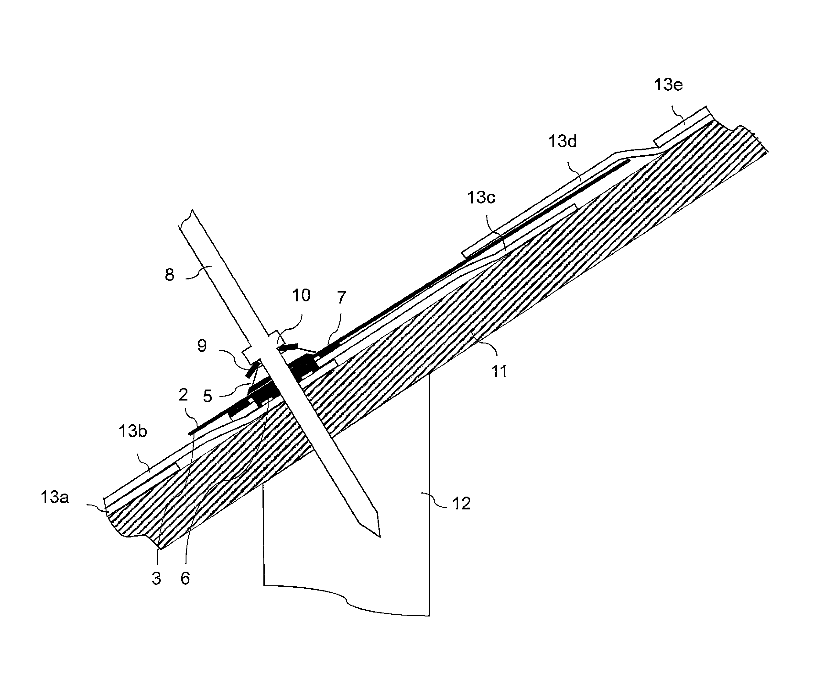
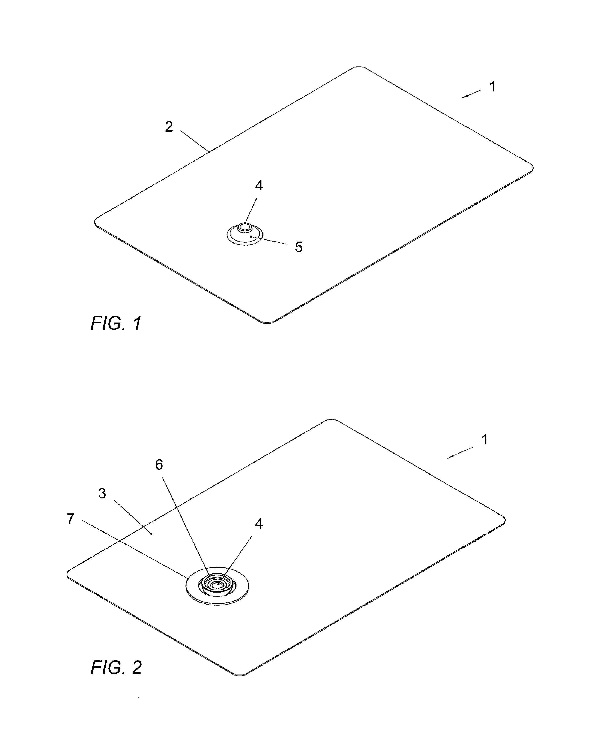
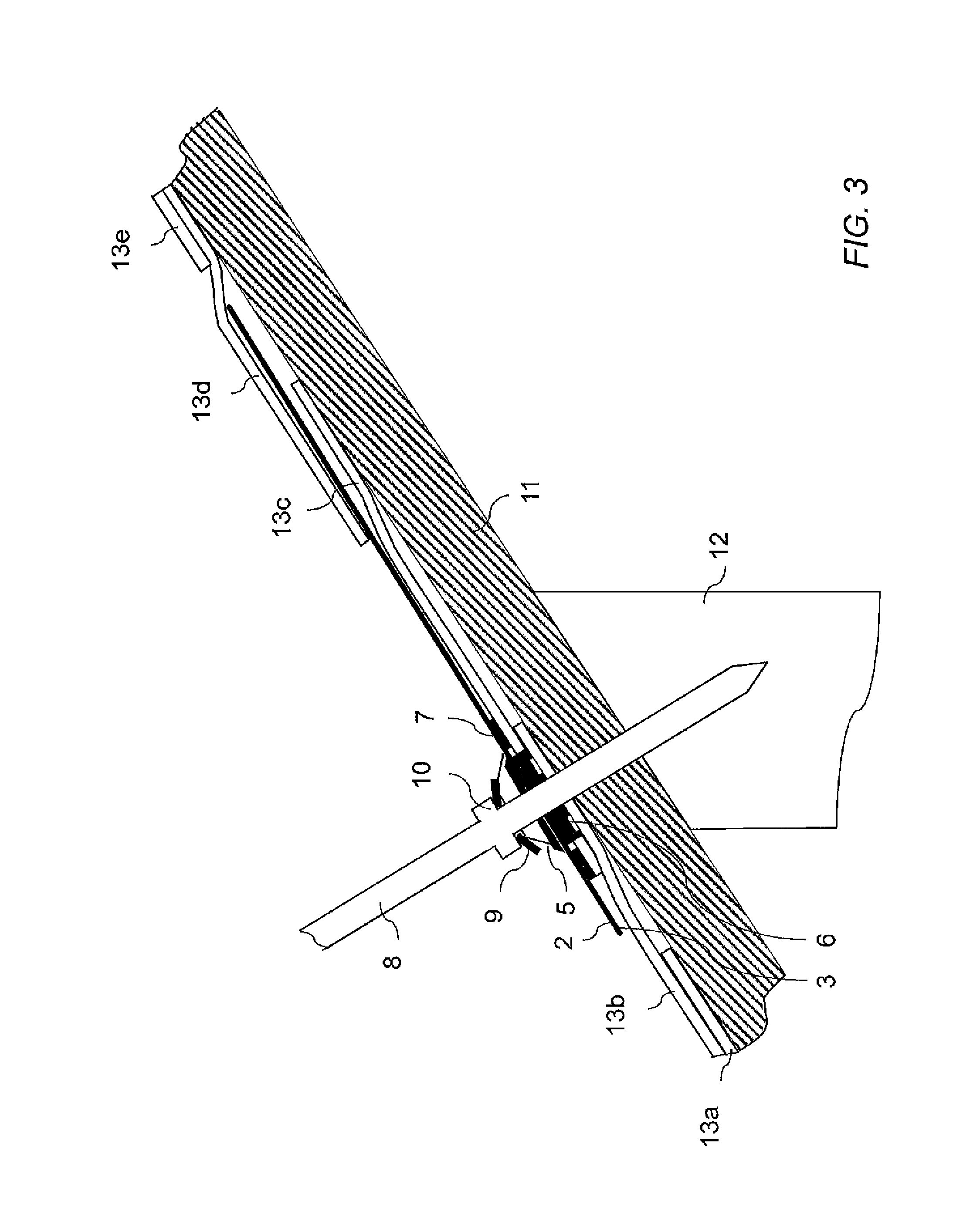
[0033]FIG. 1 shows a top view of an exemplary embodiment of a flashing system 1 according to the invention. The flashing system 1 comprises a flashing plate with an upper surface 2. The flashing plate further comprises a hole 4 therethrough, which is adapted to receive at least a portion of a fastener—not shown—therethrough. Further, an edge of the hole 4 extends upwardly projecting away from the upper surface 2 of the flashing plate, such that a flanged edge 5 is created. The ...


PUM


Abstract

The present invention provides a flashing system for roof mounting equipment which reliably prevents water from reaching the substructure of the roof. The flashing system comprises a flashing plate having upper and lower surfaces, and at least one hole extending therethrough for receiving a fastener. A first seal is arranged at the lower surface of the flashing plate, and a second seal is arranged at the lower surface of the flashing plate surrounding the first seal, wherein the thickness of the first seal is greater than the thickness of the second seal. The thickness relation is provided when the flashing system is installed and both seals are compressed. A third seal, which receives the fastener therethrough, can be provided at the upper surface of the flashing plate.

Description

CROSS-REFERENCE TO RELATED APPLICATIONS[0001]Not Applicable.FEDERALLY SPONSORED RESEARCH OR DEVELOPMENT[0002]Not Applicable.MICROFICHE / COPYRIGHT REFERENCE[0003]Not Applicable.FIELD OF THE INVENTION[0004]The present invention relates to a flashing system. More specifically, the invention relates to a flashing system for mounting equipment, as for example solar equipment, onto a roof and sealing the roof.BACKGROUND OF THE INVENTION[0005]Mounting equipment on roofs becomes more popular on residential buildings these days, for example, solar equipment is mounted on roofs for water heating purposes or for generating electricity. Residential buildings commonly have a roof comprising layers of shingles, whereby the shingles are arranged such that they partially overlap each other. The shingles serve the purpose to protect the roofs' substructure from any leakage of water in rainy conditions. However, when equipment is secured on the roof by, for example, means of fasteners, this protective...

Claims


Application Information

Patent Timeline
Patent Type & Authority Patents(United States)
IPC IPC(8): E04D1/36
CPCF24J2/5245E04D1/36F24J2002/5294Y02B10/20Y02E10/47E04D2001/307F24S25/61F24S2025/021
Inventor GENS, LOTHANSCHNEIDER, MARCO
Owner EJOT BAUBEFESTIGUNGEN GMBH
Why Eureka
Try Eureka