Refrigeration cycle apparatus

a refrigeration cycle and apparatus technology, applied in the direction of lighting and heating apparatus, machine operation mode, heating types, etc., can solve the problem of a reduction in the cop of the refrigeration cycle apparatus b>100

Active Publication Date: 2013-10-08
PANASONIC INTELLECTUAL PROPERTY MANAGEMENT CO LTD
View PDF27 Cites 10 Cited by
  • Summary
  • Abstract
  • Description
  • Claims
  • Application Information

AI Technical Summary

Benefits of technology

[0006]The present invention has been made in view of the above circumstances, and has an object to enhance further the COP of a refrigeration cycle apparatus including a refrigerant circuit and a fluid circuit through which a fluid to be heated by a refrigerant in the refrigerant circuit flows.

Problems solved by technology

As a result, the input to the compressor 103 increases, thus causing a problem of a decrease in the COP of the refrigeration cycle apparatus 100.

Method used


Image

  • Refrigeration cycle apparatus
  • Refrigeration cycle apparatus
  • Refrigeration cycle apparatus

Examples


first embodiment

Configuration of Refrigeration Cycle Apparatus

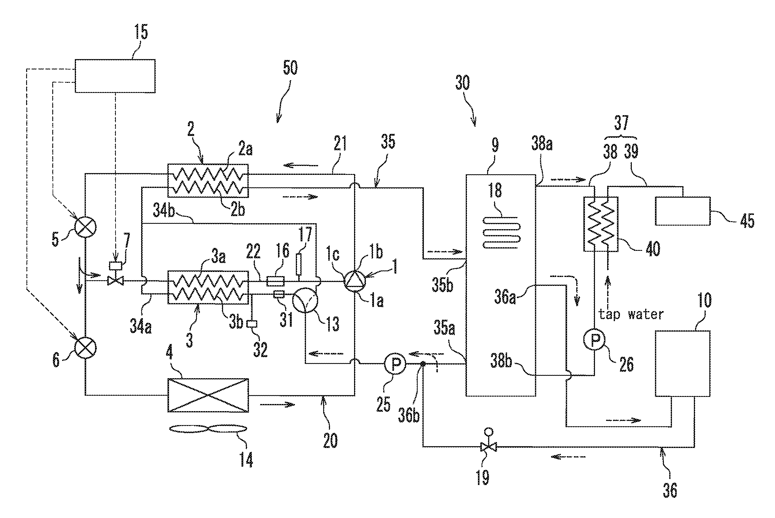
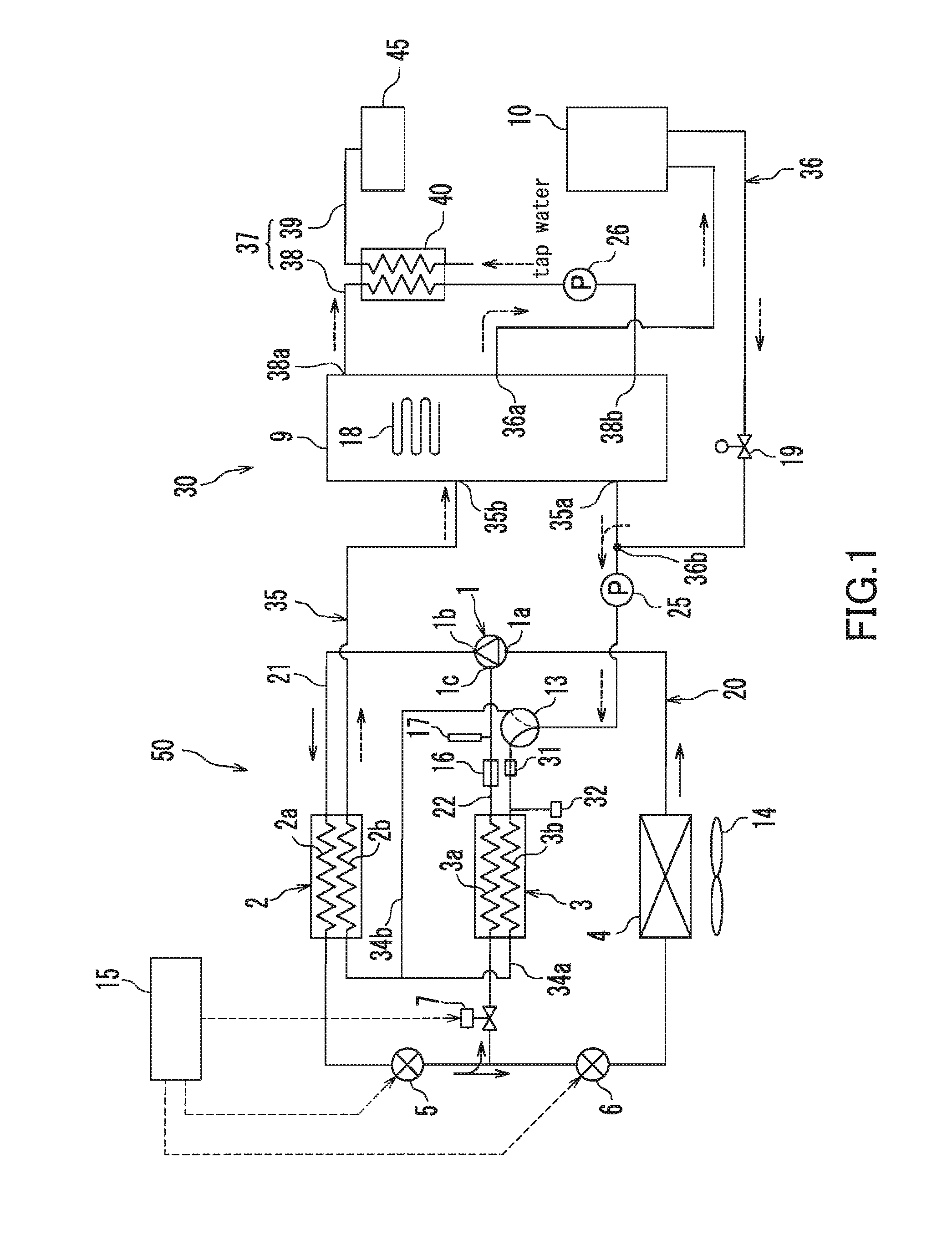
[0016]As shown in FIG. 1, a refrigeration cycle apparatus 50 according to the first embodiment constitutes a multi-functional heat pump capable of performing water heating and space heating. The refrigeration cycle apparatus 50 includes a refrigerant circuit 20 and a water circuit 30 through which water to be used for water heating or space heating flows. The refrigerant circuit 20 serves as a heat source for heating the water in the water circuit 30.

[0017]The refrigerant circuit 20 includes a main refrigerant circuit 21 and an injection passage 22. The main refrigerant circuit 21 has a compressor 1, a radiator 2, a first expansion mechanism 5, a second expansion mechanism 6, and an evaporator 4. These components are connected in a circuit in this order, and thereby form the main refrigerant circuit 21. The refrigerant circuit 20 is filled with carbon dioxide as a refrigerant.

[0018]The compressor has a suction port 1a, a discharge port 1...

second embodiment

[0072]As shown in FIG. 3, a refrigeration cycle apparatus 50B according to the second embodiment includes the refrigerant circuit 20 and a water circuit 30B. The water circuit 30B is a modified circuit of the water circuit 30 of the first embodiment. The structure of the refrigerant circuit 20 is the same as that of the first embodiment. Hereinafter, the same parts as those in the first embodiment are designated by the same reference numerals and no further description is given.

[0073]In the second embodiment, the downstream end 35b of the heat source side water circuit 35 is connected to a lower portion of the hot water storage tank 9. The structure of the heat source side water circuit 35 is the same as that of the first embodiment.

[0074]The upstream end 36a of the space heating water circuit 36 is connected to an upper portion of the hot water storage tank 9. The downstream end 36b of the space heating water circuit 36 is connected to a lower portion of the hot water storage tank ...

third embodiment

[0079]As shown in FIG. 4, a refrigeration cycle apparatus 50C according to the third embodiment includes the refrigerant circuit 20 and a water circuit 30C. The water circuit 30C is a modified circuit of the water circuit 30 of the first embodiment. The structure of the refrigerant circuit 20 is the same as that of the first embodiment. Hereinafter, the same parts as those in the first embodiment are designated by the same reference numerals and no further description is given.

[0080]The structure of the heat source side water circuit 35 is the same as that of the first embodiment.

[0081]The upstream end 36a of the space heating water circuit 36 is connected to a portion near the downstream end 35b of the heat source side water circuit 35. The downstream end 36b of the space heating water circuit 36 is connected to a portion of the heat source side water circuit 35 between the upstream end 35a thereof and the pump 25. The radiator 10 is provided in the space heating water circuit 36. ...


PUM


Abstract

A refrigeration cycle apparatus (50) includes: a main refrigerant circuit (21) having a compressor (1), a radiator (2), a first expansion mechanism (5), a second expansion mechanism (6), and an evaporator (4); an injection passage (22) for supplying an intermediate-pressure refrigerant to an injection port 1c of the compressor 1; and a water circuit (30) through which water to be heated in the radiator (2) flows. The refrigeration cycle apparatus (50) includes a sub heat exchanger (3) for cooling the water in the water circuit (30) by exchanging heat between the refrigerant in the injection passage (22) and the water to be heated in the radiator (2).

Description

TECHNICAL FIELD[0001]The present invention relates to a refrigeration cycle apparatus including a refrigerant circuit and a fluid circuit through which a fluid to be heated by a refrigerant in the refrigerant circuit.BACKGROUND ART[0002]As shown in FIG. 6, there has been known conventionally a refrigeration cycle apparatus 100 including: a fluid circuit 102 through which a fluid, such as water and brine used for water heating and space heating, for example, flows; and a refrigerant circuit 101 for heating the fluid in the fluid circuit 102. The refrigerant circuit 101 includes: a compressor 103 for compressing a refrigerant; a radiator 104 for radiating heat from the refrigerant compressed in the compressor 103; an expansion mechanism 105 for expanding the refrigerant from which heat has been radiated in the radiator 104; and an evaporator 106 for evaporating the refrigerant expanded in the expansion mechanism 105. The radiator 104 has a high-temperature side flow passage 104a throu...

Claims


Application Information

Patent Timeline
Patent Type & Authority Patents(United States)
IPC IPC(8): F25B7/00F25B41/00F25B41/04F25B27/00
CPCF24D3/08F25B9/008F24D11/0235F25B1/00Y02B30/52F24D2200/12F24D2200/24F25B1/10F25B29/003F25B2309/061F25B2339/047Y02B10/70Y02B30/126F25B2600/2509F25B2400/13F24D2220/08F24D2220/2009F24D2220/06F24D2220/209Y02B30/12
Inventor KOMORI, KOUYAKUMARU, YUICHITAMURA, TOMOICHIROHONMA, MASAYAHAYASHI, HIROKI
Owner PANASONIC INTELLECTUAL PROPERTY MANAGEMENT CO LTD
Why Eureka
Try Eureka