
Pressure compensator

a technology of pressure compensator and pressure plate, which is applied in the direction of machines/engines, sealing/packing, and borehole/well accessories. it can solve the problems of transformer electrical failure, affecting the operation of the transformer, and increasing the need for compression and expansion

Active Publication Date: 2013-10-08
HITACHI ENERGY SWITZERLAND AG
View PDF28 Cites 11 Cited by
  • Summary
  • Abstract
  • Description
  • Claims
  • Application Information

AI Technical Summary

Benefits of technology

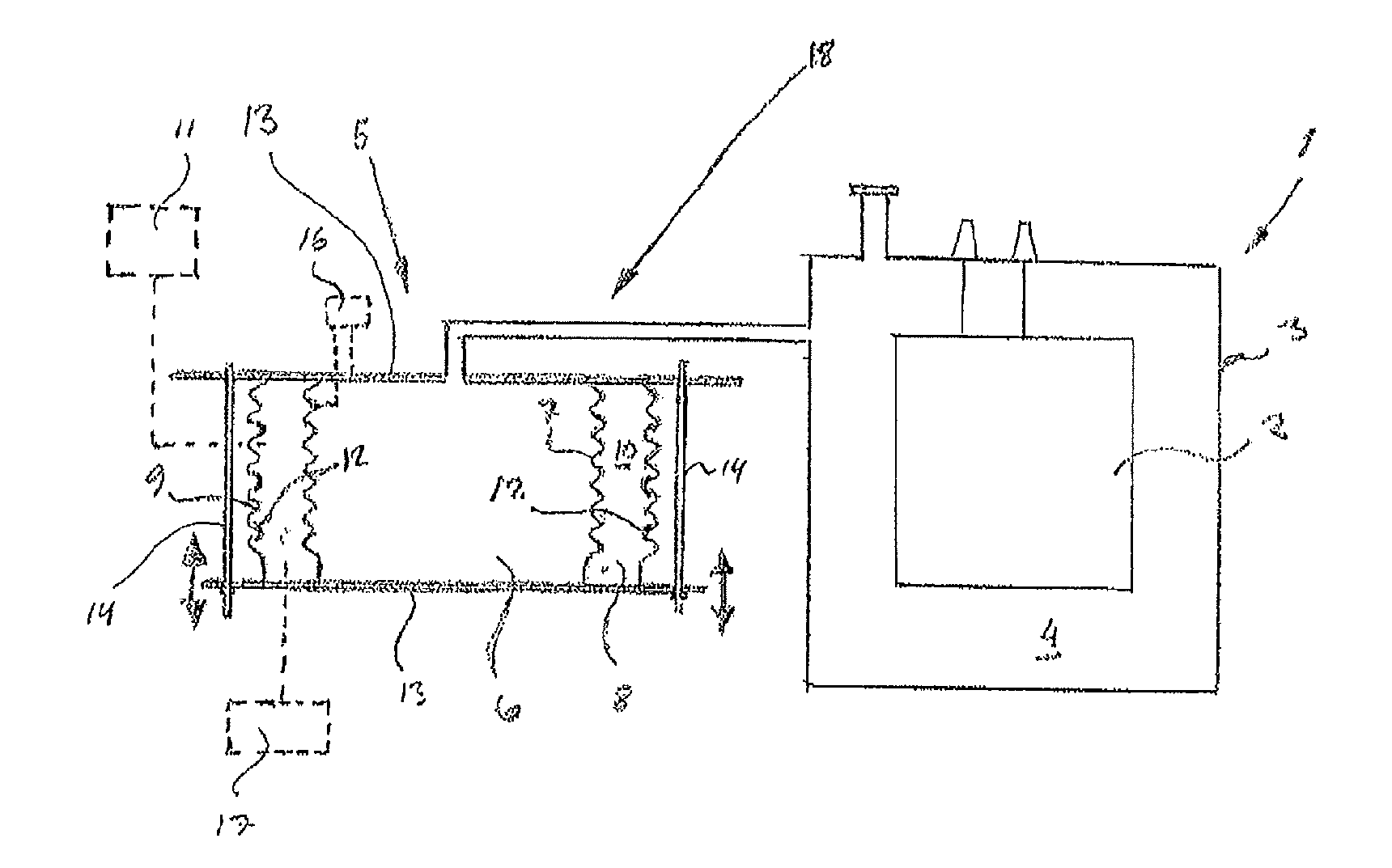
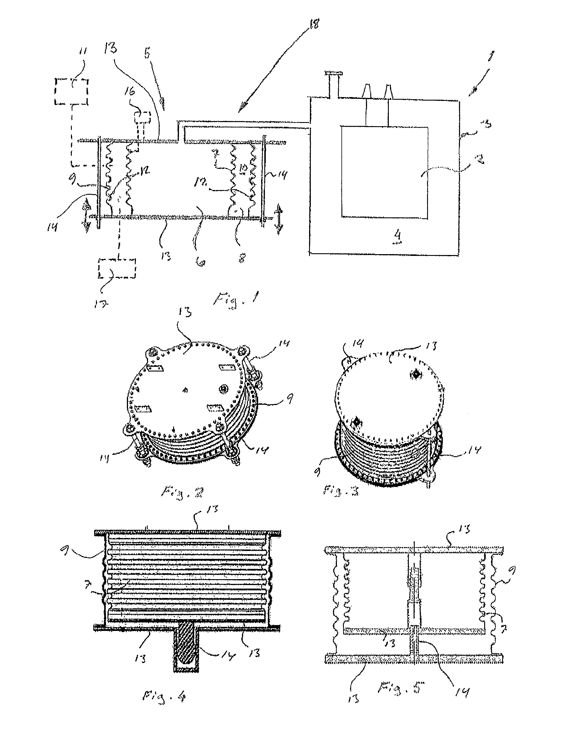
The present disclosure provides a pressure compensator for subsea installations that can compensate for volume variations of an insulation medium or liquid. The pressure compensator includes a first bellows chamber and a second bellows chamber surrounding the first chamber. The first chamber is connected to the insulation chamber and its walls separate it from sea water. The second chamber surrounds the first chamber and its walls separate it from sea water. The second chamber contains an intermediate medium. The technical effect of this design is to provide a reliable and effective way to compensate for changes in volume of the insulation medium, while preventing direct contact between sea water and the insulation material.

Problems solved by technology

As the size of a transformer tank increases, the problems and need for compression and expansion also increase accordingly.
This means that if one barrier or wall will have a failure producing leakage between the oil and the water, the water will enter into the transformer causing electrical failure of the transformer and thereby affect the operation of the transformer.
The other equipment will have also serious consequences such as electrical failures if the water will leak in.
Such leak problems relate mainly to corrosion caused by the sea water, because known pressure compensators are not particularly resistant against corrosion caused by sea water.
The sensitivity of the corrosion may be a risk with metallic bellows type pressure compensators because the wall of the bellows should be very thin to reach required flexibility.
These known solutions are not, however, suitable in subsea conditions.

Method used


Image

  • Pressure compensator
  • Pressure compensator
  • Pressure compensator

Examples


Embodiment Construction

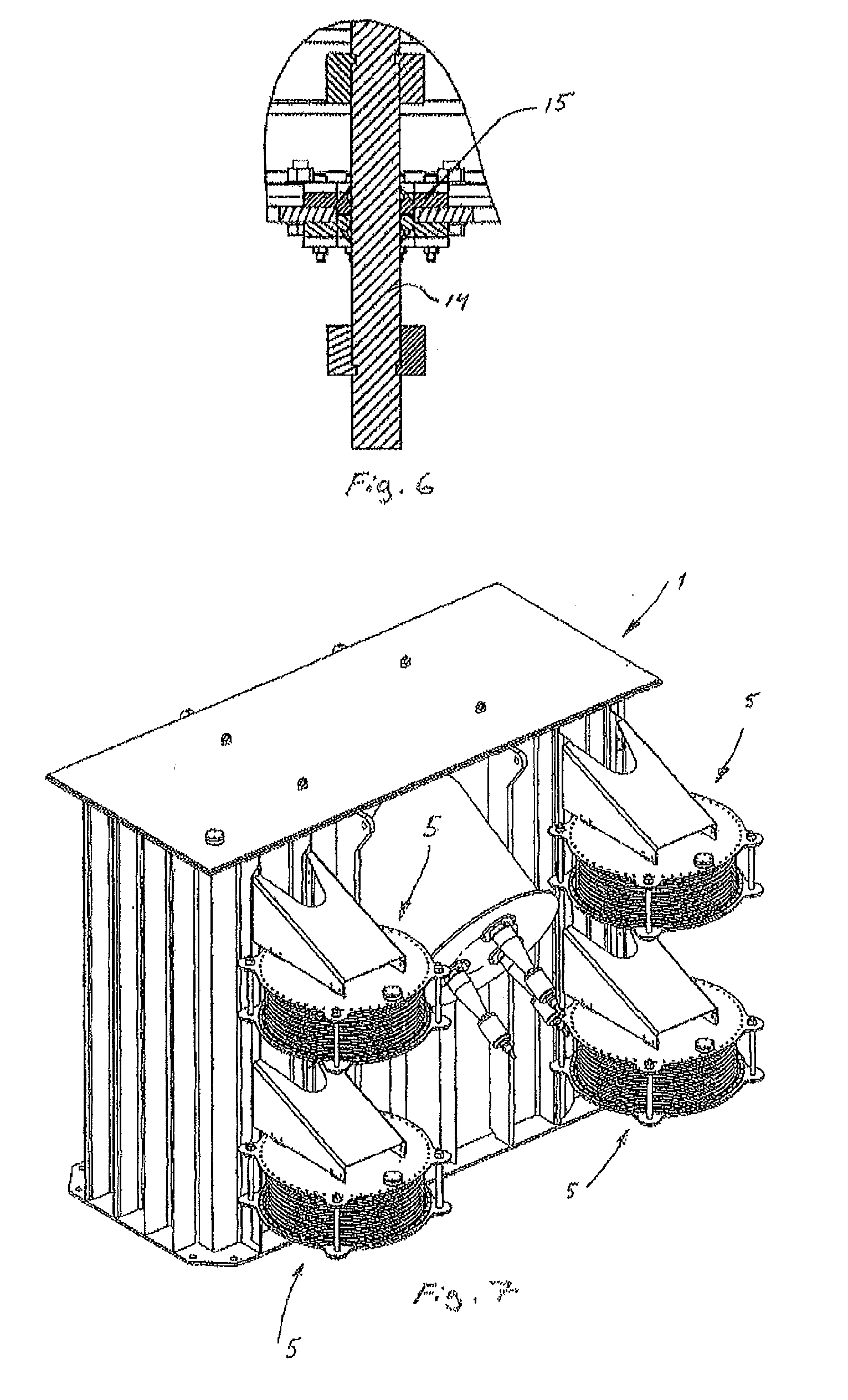
[0016]Exemplary embodiments of the present disclosure provide a pressure compensator which eliminates the problems of known solutions. Exemplary embodiments of the present disclosure provide a pressure compensator in which a first bellows chamber is surrounded by a second bellows chamber. The first bellows chamber includes a first bellows part, and the second bellows chamber includes a second bellows part. The second bellows chamber is configured to form a closed intermediate space around the first bellows chamber. The walls of the second bellows chamber are configured to separate at least the first bellows part of the first bellows chamber from the surrounding sea water. The second bellows chamber is filled with a intermediate medium, and the second bellows part of the second bellows chamber being made of a material resistant to surrounding sea water.

[0017]Exemplary embodiments of the present disclosure advantageously eliminate the problems relating to sea water corrosion. The pres...


PUM

PropertyMeasurementUnit
volumeaaaaaaaaaa
pressureaaaaaaaaaa
hydrostatic pressureaaaaaaaaaa

Abstract

A pressure compensator is configured to compensate for volume variations of an insulation medium of a subsea installation. The pressure compensator includes a first bellows chamber having walls and a first bellows part. The first bellows chamber is in flow connection with an insulation medium chamber of the subsea installation, and the walls of the first bellows chamber are configured to separate the insulating medium from surroundings. The first bellows chamber is surrounded by a second bellows chamber having walls and a second bellows part. The second bellows chamber is configured to form a closed intermediate space around the first bellows chamber. The walls of the second bellows chamber are configured to separate at least the bellows parts of the first bellows chamber from the surrounding sea water. The second bellows chamber is further filled with an intermediate medium.

Description

RELATED APPLICATION[0001]This application claims priority as a continuation application under 35 U.S.C. §120 to PCT / FI2009 / 050740, which was filed as an International Application on Sep. 16, 2009 designating the U.S., and which claims priority to European Application 08164976.6 filed in Europe on Sep. 24, 2008. The entire contents of these applications are hereby incorporated by reference in their entireties.FIELD[0002]The present disclosure relates to a pressure compensator configured to compensate volume variations of an insulation medium or other liquid of a subsea installation.BACKGROUND INFORMATION[0003]Subsea installations are assemblies used under water. Such assemblies can be installed, for example, on the bottom ground of a body of water. Power transformers are an example of subsea installations which can be used under water. Generally, power transformers use an insulation medium. For example, the power transformers can be fluid insulated having transformer oil in a transfo...

Claims


Application Information

Patent Timeline
Patent Type & Authority Patents(United States)
IPC IPC(8): G01L19/04F16L55/04
CPCE21B33/0385H01F27/14H01F27/23H05K5/068H05K7/14337
Inventor VIRTANEN, ESAHALDIN, THORVALDMISSING, KIM
Owner HITACHI ENERGY SWITZERLAND AG
Learn More