Bulk Force In A Battery Pack And Its Application To State Of Charge Estimation

a battery pack and state of charge technology, applied in battery/fuel cell control arrangement, vehicle sub-unit features, instruments, etc., can solve the problems of physics-based modeling approach very difficult, reduce separator thickness, degradation and power reduction, etc., to improve the quality discount the temperature dependence in soc estimation, and improve the effect of state of charge estimation

Active Publication Date: 2016-03-03
RGT UNIV OF MICHIGAN
View PDF1 Cites 21 Cited by
  • Summary
  • Abstract
  • Description
  • Claims
  • Application Information

AI Technical Summary

Benefits of technology

[0020]It is shown herein how to utilize bulk force measurements to improve the quality of state of charge estimates for lithium-ion cells. State of charge estimates are influenced by operating conditions and are dependent on the electrode chemistry of the cell. Measurement of the force induced in a fixture that constrains cell expansion due to SOC changes provides for more accurate SOC estimates. Force also depends on the expansion due to thermal swelling of the cell material. It is shown how to discount the temperature dependence in SOC estimation.

Problems solved by technology

A large compression, however, can decrease the separator thickness and lead to degradation and power reduction due to the separator pore closing [Ref. 2].
Moreover, the wide range of conditions with respect to C-rates and temperatures that automotive battery cells must operate make the physics-based modeling approach very challenging.
Finally, measuring and quantifying the internal stress or strain to tune or validate the multi-scale models requires complex instrumentation [Refs.

Method used


Image

  • Bulk Force In A Battery Pack And Its Application To State Of Charge Estimation
  • Bulk Force In A Battery Pack And Its Application To State Of Charge Estimation
  • Bulk Force In A Battery Pack And Its Application To State Of Charge Estimation

Examples


example 1

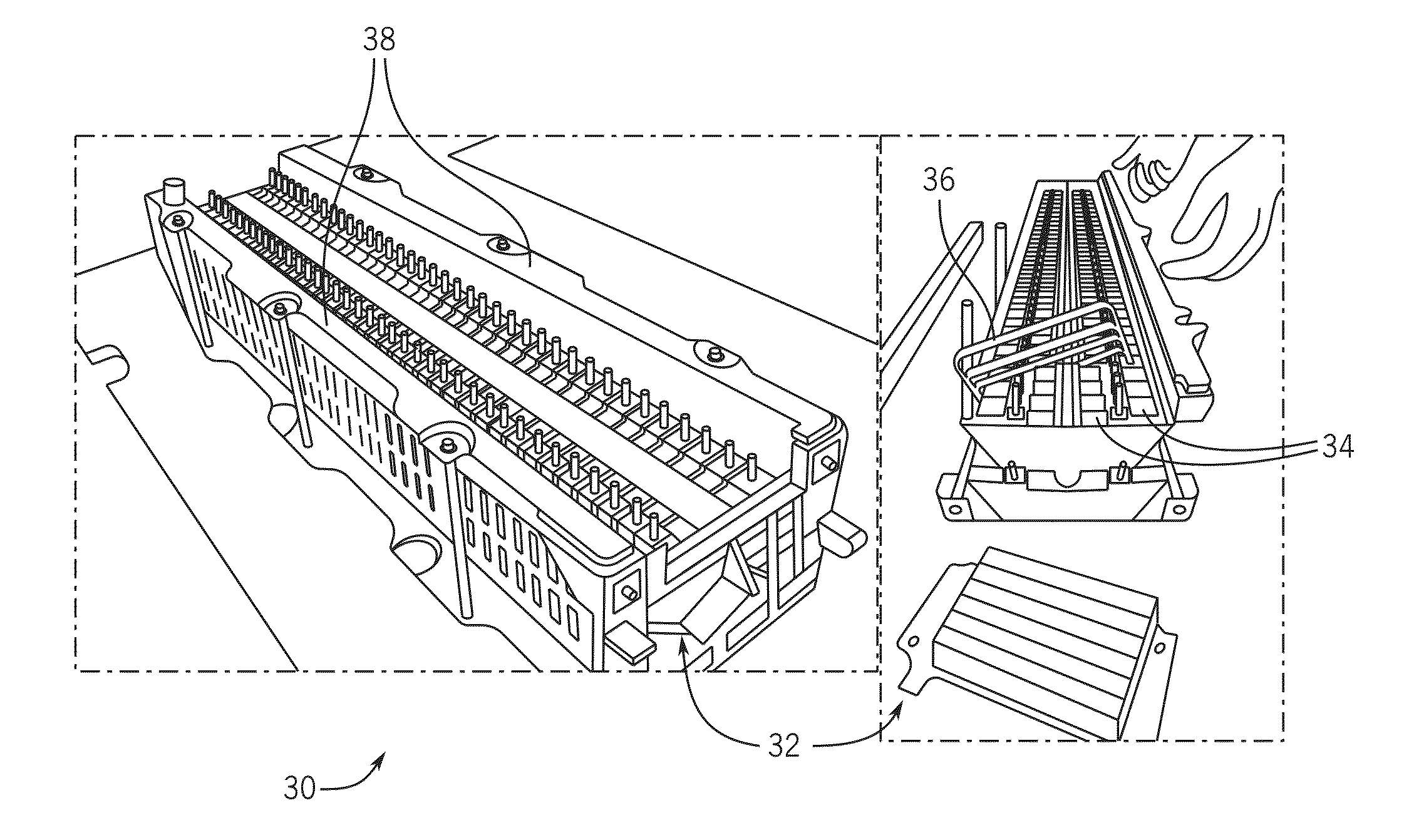
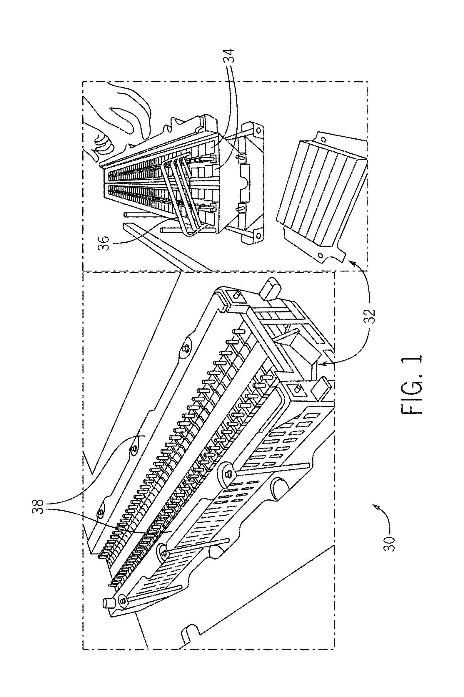
[0110]Prismatic Lithium-Nickel-Manganese-Cobalt-Oxide (NMC) batteries encased in a hard aluminum shell were used in this study. Each cell has a nominal capacity of 5 Ah and has outside dimensions of 120×85×12.7 mm. Inside the aluminum case is a horizontal flat-wound jelly roll that has dimensions 90×77.5×11.7 mm. In this orientation, with the tabs facing upwards as shown in FIG. 3, the bulk of the electrode expansion materializes as linear outward displacement of the sides of the aluminum case under unconstrained and free swelling [Ref. 13]. The packaging of the jelly roll makes the electrode expand primarily perpendicular to the largest face of the battery due to the wound structure and gaps between the electrode and casing around the top and bottom. This observed cell expansion is, consequently, exerted against the end-plates 32 when the battery pack 30 is assembled as shown in FIG. 1. The space between the batteries 34 is maintained via a plastic spacer 36 with dimples to preserv...

example 2

[0154]In this Example, the electrical dynamics of the cell is represented by a two-state impedance model whose dynamics is shown in Equation (11). Equation (11) is obtained by discretizing the continuous-time dynamic equations using backward discretization method with sampling period of duration Ts seconds. In the following, an underscript is used to denote the value of the variable at a particular sample.

zk+1=zk+TsIkQυk+11=(1-TsC1(zk)R1(zk))υk1+IkTsC1(zk)υk+12=(1-TsC2(zk)R2(zk))υk2+IkTsC2(zk)Vk=IkRs(zk)+υk1+υk2+Voc(zk)Fk=f~(zk)(11)

where z is the SOC of the cell, Q is proportional to the capacity of the cell, C1(z), C2(z), R1(z), R2(z) are functionals that represent the dependence of the impedance model parameters on SOC. VOC(z) is the SOC dependent open circuit voltage of the cell; I is the current (charging current is positive); ν1, ν2 are polarization voltages; RS is ohmic resistance of the cell; terminal voltage is denoted by V; and {tilde over (f)}(z) is a functional that repre...


PUM


Abstract

There is disclosed an electrical device including a battery pack, a pressure sensor for measuring a volume change of the battery pack, a voltage sensor in electrical communication with a positive terminal and a negative terminal of the battery pack, a temperature sensor positioned in a cell of the battery pack, and a battery management system. The battery management system includes a controller in electrical communication with the pressure sensor, the voltage sensor, and the temperature sensor, the controller being configured to execute a program stored in the controller to determine a state of charge percentage of the battery pack based on a pressure reading from the pressure sensor, a terminal voltage reading from the voltage sensor, and a temperature reading from the temperature sensor.

Description

CROSS-REFERENCES TO RELATED APPLICATIONS[0001]This application claims priority from U.S. Patent Application No. 62 / 043,519 filed Aug. 29, 2014.STATEMENT REGARDING FEDERALLY SPONSORED RESEARCH[0002]This invention was made with government support under number DE-AR0000269 awarded by the U.S. Department of Energy. The government has certain rights in the invention.BACKGROUND OF THE INVENTION[0003]1. Field of the Invention[0004]This invention relates to an electrical device including a battery pack and a battery management system that determines a state of charge percentage of the battery pack based, at least in part, on a pressure reading from a pressure sensor adjacent the battery pack, a terminal voltage reading from the battery pack, and a temperature reading from the battery pack. More particularly, the invention relates to bulk forces exerted by a lithium on cell during various operating conditions and their effects on state of charge.[0005]2. Description of the Related Art[0006]V...

Claims


Application Information

Patent Timeline
Patent Type & Authority Applications(United States)
IPC IPC(8): H02J7/00G01R31/36
CPCH02J7/0021G01R31/3634G01R31/3655G01R31/387Y02T10/70Y02E60/10H02J7/0013H02J7/0048H01M10/48B60L2240/547B60L2240/545B60Y2400/3086B60Y2400/306B60Y2400/302B60L58/12B60Y2200/91B60Y2200/92Y02T10/7072
Inventor STEFANOPOULOU, ANNA, G.MOHAN, SHANKAR, NARAYANKIM, YOUNGKISIEGEL, JASON, B.
Owner RGT UNIV OF MICHIGAN
Why Eureka
Try Eureka