Variable displacement pump

Inactive Publication Date: 2015-09-10
HITACHI AUTOMOTIVE SYST LTD
View PDF25 Cites 21 Cited by
  • Summary
  • Abstract
  • Description
  • Claims
  • Application Information

AI Technical Summary

Benefits of technology

[0004]However, in the case of the previously-proposed variable displacement pump, only two control oil chambers which control the movement of the cam ring are provided. Hence, the pump discharge pressure attains only two levels of the low-pressure characteri

Problems solved by technology

However, in the case of the previously-proposed variable displacement pump, only two control oil chambers which control the movement of the cam ring are provided.
Accordingly, in the case of the previously-proposed variab

Method used


Image

  • Variable displacement pump
  • Variable displacement pump
  • Variable displacement pump

Examples


first embodiment

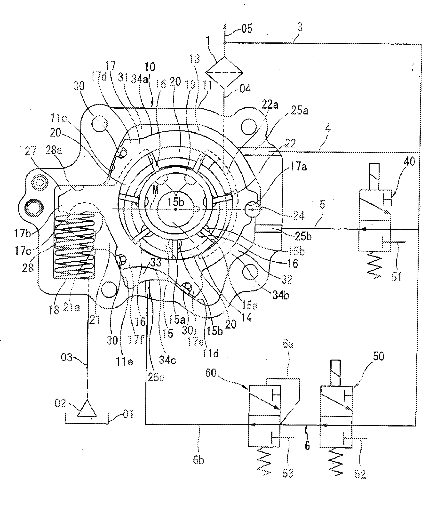
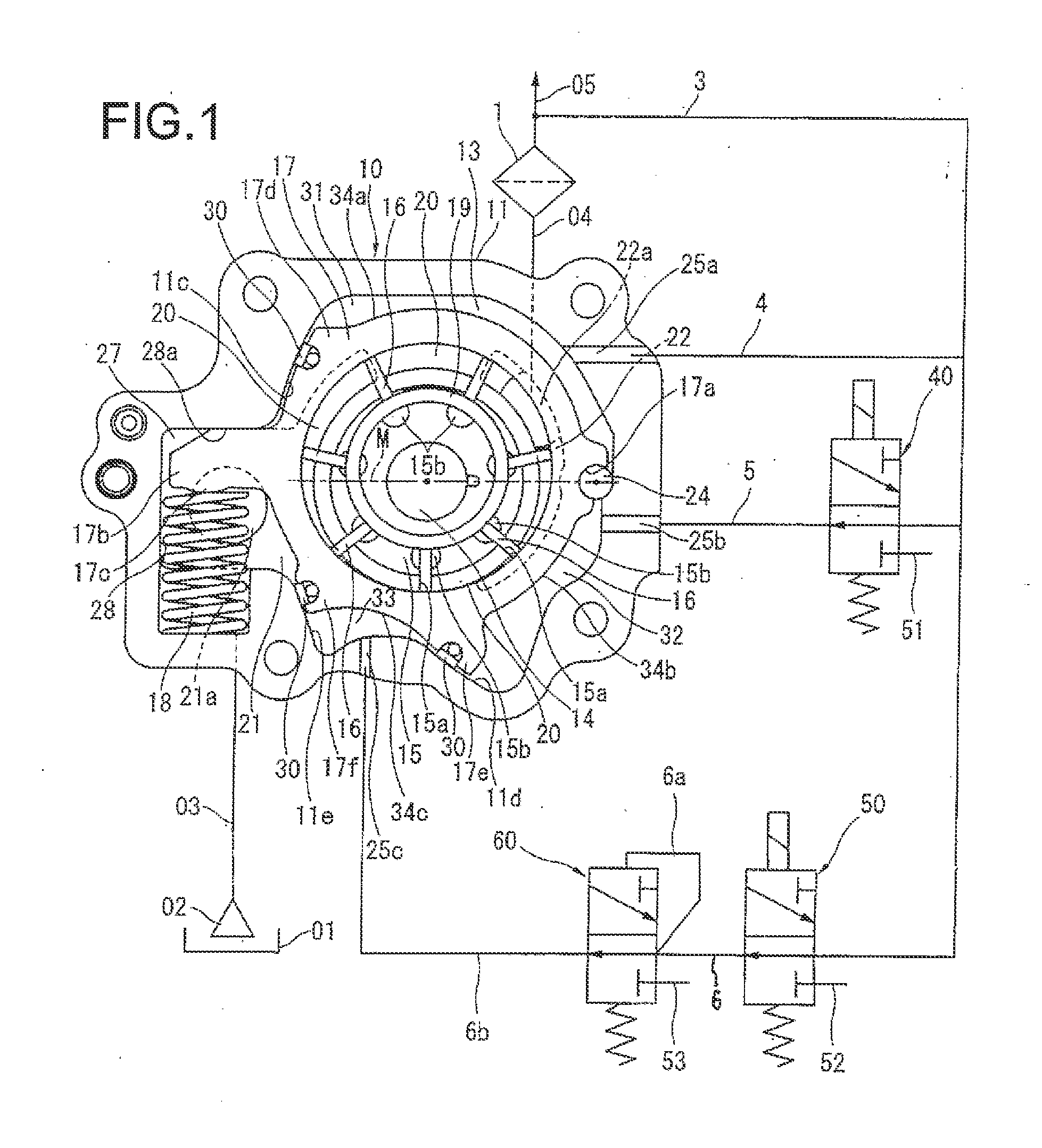
[0037]FIG. 1 shows an oil-pump portion and a hydraulic circuit in the variable displacement pump of a first embodiment according to the present invention. An oil pan 01 retains oil. The oil pump 10 rotates by rotary drive force derived from the crankshaft of the internal combustion engine, and thereby sucks oil from the oil pan 01 through a strainer 02 and a suction passage 03 and discharges oil through a discharge passage (discharge portion) 04 to a main oil gallery 05 of the engine.

[0038]From the main oil gallery 05, oil is supplied to the sliding portions of the engine (e.g., the oil jet for spraying cooling oil to the piston), the valve-timing control device, and the bearing of the crankshaft. An oil filter 1 is disposed in the main oil gallery 05 at a location downstream of the discharge passage 04. The oil filter 1 collects foreign substances which exist within the flowing oil.

[0039]A control passage 3 branches off from the main oil gallery 05 at a location downstream of the o...

second embodiment

[0110]FIG. 11 shows a second embodiment according to the present invention. A configuration of the second embodiment is the same as the above-mentioned configuration of the first embodiment, except that the first electromagnetic changeover valve 40 and the second electromagnetic changeover valve 50 (of the first embodiment) are collected as a single electromagnetic changeover valve 70.

[0111]The electromagnetic changeover valve 70 has five ports and three stages. As shown in FIGS. 12A to 12C, the electromagnetic changeover valve 70 includes a valve body 71 and a solenoid unit 72. The valve body 71 is inserted into and fixed to the cylinder block. The solenoid unit 72 is provided at a rear end portion of the valve body 71.

[0112]The valve body 71 is formed with a valve hole 73 which extends in an axial direction of the valve body 71 inside the valve body 71. A spool valve 74 is provided to be able to slide in the valve hole 73 in the axial direction of the valve body 71. A peripheral w...

third embodiment

[0139]FIG. 18 shows a third embodiment according to the present invention. A configuration of the third embodiment is the same as the above embodiments, except the following. In the third embodiment, although the third control oil chamber is not provided, and a fourth control oil chamber 90 is provided between the stopper surface 28a of the spring receiving chamber 28 and the upper surface of the arm portion 17b. The fourth control oil chamber 90 cooperates with the first control oil chamber 31 to constitute the reduction-side oil chamber group.

[0140]The fourth control oil chamber 90 is able to communicate with the discharge passage 04 through a second control passage 93 which branches off from the discharge passage 04. A third electromagnetic changeover valve 91 is provided in the middle of the second control passage 93. Hydraulic pressure is supplied through the third electromagnetic changeover valve 91 to the fourth control oil chamber 90, and thereby an internal pressure of the ...


PUM


Abstract

A variable displacement pump includes a variable mechanism configured to change a volume-variation rate of each pump chamber by movement of a movable member; a biasing mechanism provided to bias the movable member in a direction that increases the volume-variation rate; at least one reduction-side control oil chamber to which oil is supplied from a discharge portion such that the reduction-side control oil chamber applies force to the movable member in a direction that reduces the volume-variation rate; at least one increase-side control oil chamber to which oil is supplied from the discharge portion such that the increase-side control oil chamber applies force to the movable member in the direction that increases the volume-variation rate; and a control mechanism configured to control a oil quantity which is supplied to each control oil chamber. The total number of the control oil chambers is three or more.

Description

BACKGROUND OF THE INVENTION[0001]The present invention relates to a variable displacement pump adapted to supply working fluid.[0002]U.S. Patent Application Publication No. 2010 / 226799 (corresponding to Japanese Patent Application Publication No. 2010-209718) discloses a previously-proposed variable displacement pump.[0003]The variable displacement pump disclosed in this patent application is a so-called vane pump. In this technique, the variable displacement pump includes a first control oil chamber, a second control oil chamber and an electromagnetic changeover valve. The first control oil chamber and the second control oil chamber are formed radially outside a cam ring and separated from each other. The first control oil chamber receives a pump discharge pressure and thereby applies force to the cam ring in a direction that reduces an eccentricity amount of the cam ring whereas the second control oil chamber receives the pump discharge pressure and thereby applies force to the ca...

Claims


Application Information

Patent Timeline
IPC IPC(8): F04C14/22F04C15/00F01M1/02F04C2/344
CPCF04C14/226F01M1/02F04C15/008F04C2/3442F01M1/16F01M2001/0238F01M2001/0246F04C2/344F04C2270/185
Inventor OHNISHI, HIDEAKIWATANABE, YASUSHI
Owner HITACHI AUTOMOTIVE SYST LTD
Why Eureka
Try Eureka