Novel swirl dispersing device

A dispersing device and swirl technology, which is applied in the field of swirl technology and new devices, can solve the problems of low processing capacity, rapid fall into the bottom of the tower or adhesion to the tower wall, and small airflow resistance, so as to avoid temperature and concentration fluctuations. Uniformity, avoiding the sinking of solid materials, and reducing the effect of liquid film resistance

Inactive Publication Date: 2014-11-05
XIAMEN UNIV
View PDF6 Cites 22 Cited by
  • Summary
  • Abstract
  • Description
  • Claims
  • Application Information

AI Technical Summary

Problems solved by technology

The traditional spray head is fixed and cannot form a liquid swirl, and the swirl effect generated by the introduction of gas is limited. Under the action of gravity and initial kinetic energy, the liquid quickly falls to the bottom of the tower or adheres to the wall of the tower, and there is a serious wall flow. and wall sticking phenomenon, so the gas-liquid contact time and opportunities are limited, and the mass and heat transfer effect needs to be improved
At present, equipment with larger diameter and height is used to ensure its effect. Therefore, the size of the equipment is too large, the processing capacity is not large, and the dust entrainment is serious, etc.
[0006] (4) Cooling heat exchange: the best form of heat exchange is direct contact heat exchange of materials, the heat exchange effect is subject to the contact area and contact time, spray bed and fluidized bed are the best forms of direct contact heat exchange, but the contact time The heat exchange efficiency needs to be improved; the slurry bed with built-in or external heat exchanger is an ideal heat exchange reaction equipment for indirect contact heat exchange, but it is limited by the heat transfer resistance of liquid film
Mechanical dust removal relies on mechanical force to remove dust particles from the airflow. It has a simple structure, low equipment and operating costs, but the dust removal efficiency is not high.
Electrostatic dust removal uses electrostatic attraction to separate dust particles from a large amount of airflow. It is characterized by small airflow resistance and a dust removal efficiency of over 99%. However, the investment is high, the size of the equipment is large, the heat loss is large, and waste heat recovery is difficult
The filter dust collector is to make the dust-laden air flow pass through the filter material to collect dust particles. The dust removal efficiency is generally 90% to 99%, but it is not suitable for dust-laden gases with high temperature. The above-mentioned dust removal methods need to be desulfurized separately. There is also secondary dust pollution during the transfer process
[0009] Water washing, dedusting and desulfurization is the most commonly used flue gas purification method. It is to make dust particles, sulfur dioxide, nitrogen oxides and other pollutants fully contact with liquid droplets or liquid films in the air or on the surface of the filler by spraying dilute alkaline water. Captured, the dust removal efficiency is 80% to 95%, and can remove harmful gases such as sulfur dioxide and nitrogen oxides at the same time, but due to large gas volume, small water volume, poor dispersion, short contact time, and unsatisfactory interphase contact effect, there is still purification effect Poor, high energy consumption and high disposal costs

Method used


Image

  • Novel swirl dispersing device
  • Novel swirl dispersing device
  • Novel swirl dispersing device

Examples


Embodiment 1

[0055] The heat transfer effect comparison of gas swirl or not in embodiment 1 spray tower

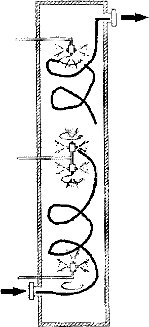
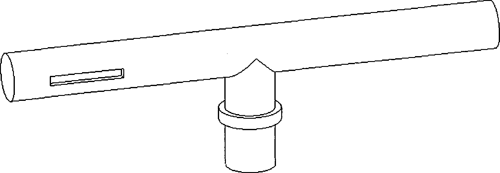
[0056] In a tower with a diameter of 300mm and a height of 1000mm, use hot water with a flow rate of 200L / h and 61°C to spray from the top of the tower, 60m 3 / h The air is ejected from opposite directions at both ends of the movable air duct at the bottom of the tower, and the reaction force of the gas causes the nozzle to rotate to form a gas swirl. For details of the simple swirl device, see Image 6 .

[0057] Use hot water of the same temperature to atomize and spray from the top of the tower, and through the temperature difference of the liquid collected at the top and bottom of the tower, the tendency of the surface of the atomized water droplets to vaporize into the gas phase can be judged, and the heat transfer effect can be evaluated.

[0058] Such as Figure 7 As shown, the temperature drop trend in the case of mixed cyclone flow is significantly greater than that in the c...

Embodiment 2

[0059] The mass transfer effect comparison of gas swirl in embodiment 2 spray tower

[0060] In a tower with a diameter of 300mm and a height of 1000mm, use 0.1% NaOH solution with a flow rate of 200L / h to spray from the top of the tower, CO 2 (2%)~The air mixture is sprayed from opposite directions at both ends of the movable air guide pipe at the bottom of the tower. The reaction force of the gas causes the nozzle to rotate and form a gas swirl. See Image 6 .

[0061] Use NaOH solution with the same concentration and the same initial conductance value to atomize and spray from the top of the tower, and measure the conductance value change of the liquid collected at the bottom of the tower, according to the CO with gas swirl and gas without swirl 2 (2%)~The change in the conductance value of the reaction between the air mixture and the alkali can judge whether the gas swirl is under the condition of liquid film control to improve the mass transfer effect.

[0062] as attac...

Embodiment 3

[0063] Embodiment 3 stirring performance effect evaluation

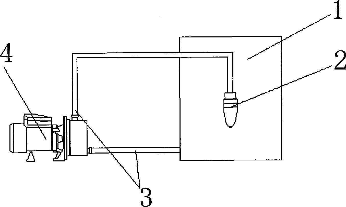
[0064] Put 500L of clean water in a container with a diameter of 1500mm and a height of 1000mm. The rotary nozzle is connected to the outlet pipe of the pump and placed in the solution. The inlet pipe of the pump is placed in the solution to allow material circulation. The pressure and flow of the pump can be changed. The rotation speed and the spraying distance of the rotating nozzle optimize the mixing effect. The mechanical stirrer in the comparative experiment was installed on the top of the container, and the three-blade propeller-type stirring paddle was placed in the same position in the solution through the stirring shaft.

[0065] By adding NaCl solution with the same solubility from the upper part or inside the nozzle in the same volume of water, and measuring the change trend of the conductance value and the equilibrium time at any point, the mixing effect under various comparison conditions can be well ju...


PUM


Abstract

The invention relates to a novel swirl dispersing device which mainly includes a rotating spray nozzle, a pump, a container and pipelines. Energy in transmission processes, which is not concerned up to now, are successfully applied in various reaction processes and mass and heat transmission processes intelligently. Rotation is generated by means of kinetic energy of system input or circulating materials and a pressure gradient is formed through a rapid change of a gas temperature or / and a volume change due to absorption. A tornado-like effect can be automatically induced in a gas phase and a swirl-like flow is forcedly formed in a liquid phase so that a mixing effect which is better than that generated from mechanical stirring and a circulator, thereby significantly increasing a mass and heat transmission efficiency in various processes. The novel swirl dispersing device is an important innovation of devices in process intensification, is simple and practical, is low in cost, is energy-saving and high-efficient, has a long effective distance, is good in the effects of mass and heat transmission and dispersion and separation, is wide in application and is strong in universality. The novel swirl dispersing device can solve uniform mass and heat transmission in a gas-phase system, a liquid-phase system, a gas-liquid system, a gas-solid system and a gas-liquid-solid system.

Description

technical field [0001] The invention relates to a swirling flow technology and a novel device capable of significantly improving the process intensification effect, and belongs to the field of chemical technology and mechanical equipment. Background technique [0002] The mass transfer heat transfer and reaction separation process in gas phase, liquid phase, gas-liquid two-phase, gas-solid two-phase and gas-liquid-solid three-phase system usually adopts the following mixing or separation forms: [0003] (1) Fully mixed tank reactor: It is often used in the process of mixing and dispersing liquid-liquid, gas-liquid, liquid-solid, and gas-liquid-solid systems with liquid as the continuous phase and gas or solid as the dispersed phase. The device is mainly composed of a motor that generates power, a reducer that adjusts the speed, a transmission stirring shaft and various forms of stirring paddles that promote the mixing of materials. The liquid can be added in stages or contin...

Claims


Application Information

Patent Timeline
Patent Type & Authority Applications(China)
IPC IPC(8): B01F5/00B01F5/20B01F13/02B01F15/06B01D50/00B01D47/06B01D53/78B01D53/60B01J19/26B01F33/40
Inventor 翁慧超尹应武吴延庆赖永华李大川崔建斌严格鲍伟超王泉叶李艺赵玉芬
Owner XIAMEN UNIV
Why Eureka
Try Eureka