Multi-component orthodontic bracket assembly

a bracket and multi-component technology, applied in the field of orthodontic brackets, can solve the problems of complex and time-consuming bracket repositioning or “replacement”, relatively the same kind of cost and discomfort, and the process is uncomfortable for the patient and is relatively costly

Active Publication Date: 2013-10-08
COLLINS MONTE
View PDF70 Cites 52 Cited by
  • Summary
  • Abstract
  • Description
  • Claims
  • Application Information

AI Technical Summary

Benefits of technology

[0011]In accordance with the present invention, an orthodontic bracket assembly adapted for securement to teeth of the upper and lower jaw is provided. The assembly is a multi-component system that includes a base component and a bracket component. The base component is designed to be bonded to a tooth and includes a peripheral housing having an integral channel guide. The bracket component includes a flange arranged for insertion within the channel guide and is held therein by a spring clip. The bracket component includes an archwire retention head for receiving and retaining an orthodontic archw

Problems solved by technology

While such prior and currently utilized bracket systems do allow therapeutic pressure to be applied to a patient's teeth, they suffer from some drawbacks.
This “bracket repositioning” or “replacement” is complicated and time consuming because the currently utilized brackets must be forcibly removed from the patient's teeth (e.g., removed from the cement or adhering agent), the teeth must be cleaned and “re-prepped” (an etching agent and a new application of an adhering agent must be deployed on the teeth), and the new or modified brackets must be replaced on the newly prepped teeth.
The process is uncomfortable to the patient and is relatively costly due to the need for additional etching and adhesive material and the time needed to achieve the change or modification.
Moreover, sometimes

Method used


Image

  • Multi-component orthodontic bracket assembly
  • Multi-component orthodontic bracket assembly
  • Multi-component orthodontic bracket assembly

Examples


Embodiment Construction

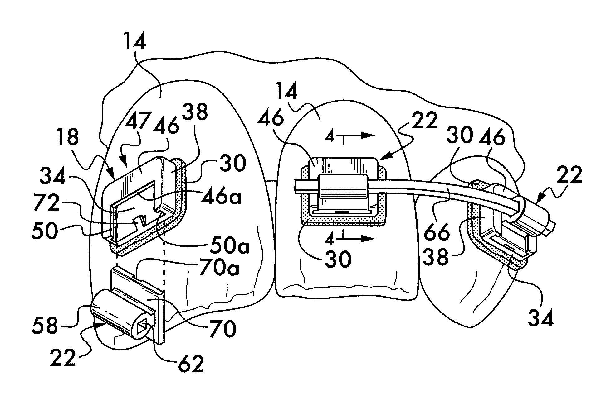
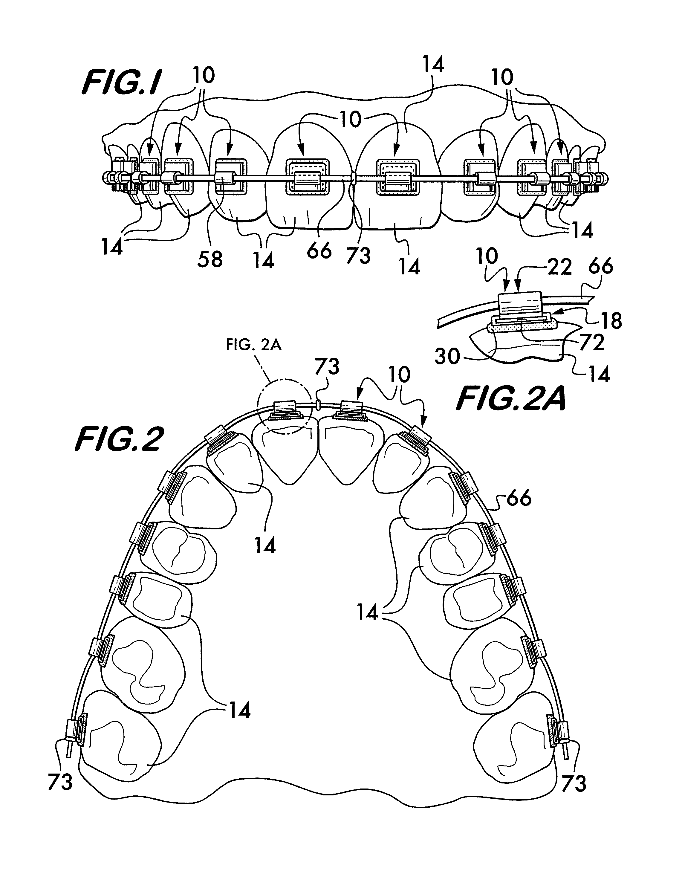
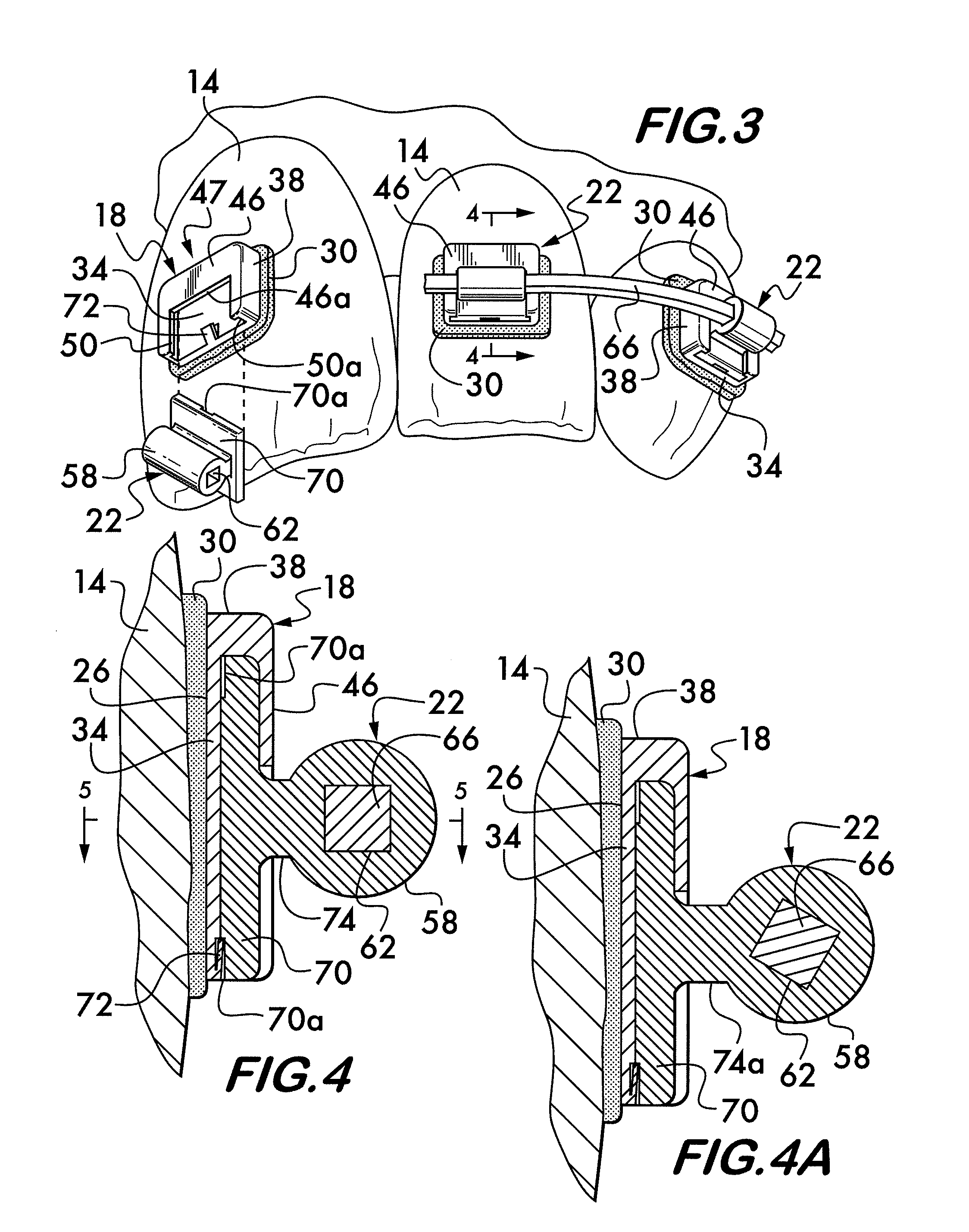
[0032]Referring now in detail to the various figures of the drawings wherein like reference characters refer to like parts, there is shown at 10 in FIGS. 1-3, a first embodiment of the present invention. The first embodiment includes a plurality of orthodontic brackets 10 bonded to the front surface of a plurality of adjacent teeth 14 of the maxilla, or upper jaw, of a patient, the teeth 14 requiring corrective orthodontic alignment. It should be understood that alternatively, the orthodontic brackets 10 of the present invention could be applied to adjacent teeth of the lower jaw, or of both the upper and lower jaws. Referring now to FIG. 3, each of the orthodontic brackets 10 is a multi-component system including a base component 18 adapted to be secured to the tooth and a bracket component 22 arranged to be retained within the base component 18.

[0033]Referring now to FIGS. 3-5, each base component 18 includes a back surface 26 which is arranged for attachment to a tooth 14 utilizi...


PUM


Abstract

An orthodontic bracket assembly adapted for securement to teeth of the upper and lower jaw is provided. The assembly is a multi-component system that includes a base component and a bracket component. The base component is adapted for securement to a tooth using an adhesive material and includes a housing having an integral channel guide. The bracket component includes a flange arranged for insertion within the channel guide and is held therein by a spring clip. The bracket component includes an archwire retention head for receiving and retaining an orthodontic archwire therein. In one embodiment, the archwire retention head includes a tube having an archwire tunnel extending mesial-distally therethrough. The cross-sectional shape of the archwire tunnel can vary depending upon the archwire being employed and may provide a frictional or frictionless fit. The tube may be positioned at a predetermined location for correcting a maloccluded tooth.

Description

CROSS-REFERENCE TO RELATED APPLICATIONS[0001]“Not Applicable”STATEMENT REGARDING FEDERALLY SPONSORED RESEARCH OR DEVELOPMENT[0002]“Not Applicable”INCORPORATION-BY-REFERENCE OF MATERIAL SUBMITTED ON A COMPACT DISK[0003]“Not Applicable”FIELD OF THE INVENTIONBACKGROUND OF THE INVENTION[0004]Orthodontic brackets, often referred to as “braces”, are dental devices used to guide tooth movement during orthodontic treatment. Brackets are manufactured with specific “prescriptions” which are designed to produce ideal positions of the teeth based on average anatomical size and shape of the teeth. Brackets are typically manufactured in specific dimensions, with the most common sizes of brackets having working surfaces (slots) in 0.018×0.025 inch and 0.022×0.025 inch dimensions. Either of these measurements allows for an arch wire of similar dimension to be placed in the slot and used to assist in the movement of teeth.[0005]These brackets are typically made of either stainless steel, titanium, p...

Claims


Application Information

Patent Timeline
IPC IPC(8): A61C3/00
CPCA61C7/12A61C7/143A61C7/22A61C7/282A61C7/287
Inventor COLLINS, MONTE
Owner COLLINS MONTE
Why Eureka
Try Eureka