Self-contained tubular compressed-flow generation device for use in making differential measurements

Active Publication Date: 2013-10-15
NASA
View PDF17 Cites 1 Cited by
  • Summary
  • Abstract
  • Description
  • Claims
  • Application Information

AI Technical Summary

Benefits of technology

The present invention provides a device for making differential measurements in a flowing fluid. The device can be easily installed in an existing conduit or duct, and can provide accurate and reliable data for monitoring fluid flow.

Problems solved by technology

This can be time consuming, tedious, and costly.
This is especially problematic when making differential measurements (i.e., at two spaced apart locations along a conduit) as multiple devices must be spliced into a conduit with the entire installation then requiring calibration to account for installation irregularities.
Still further, current differential flow measurement devices can create substantial pressure losses effecting pump efficiency.
For example, a flow measurement device such as an orifice plate is readily clogged with debris thereby impacting flow measurements and the flow itself.

Method used


Image

  • Self-contained tubular compressed-flow generation device for use in making differential measurements
  • Self-contained tubular compressed-flow generation device for use in making differential measurements
  • Self-contained tubular compressed-flow generation device for use in making differential measurements

Examples


Embodiment Construction

)

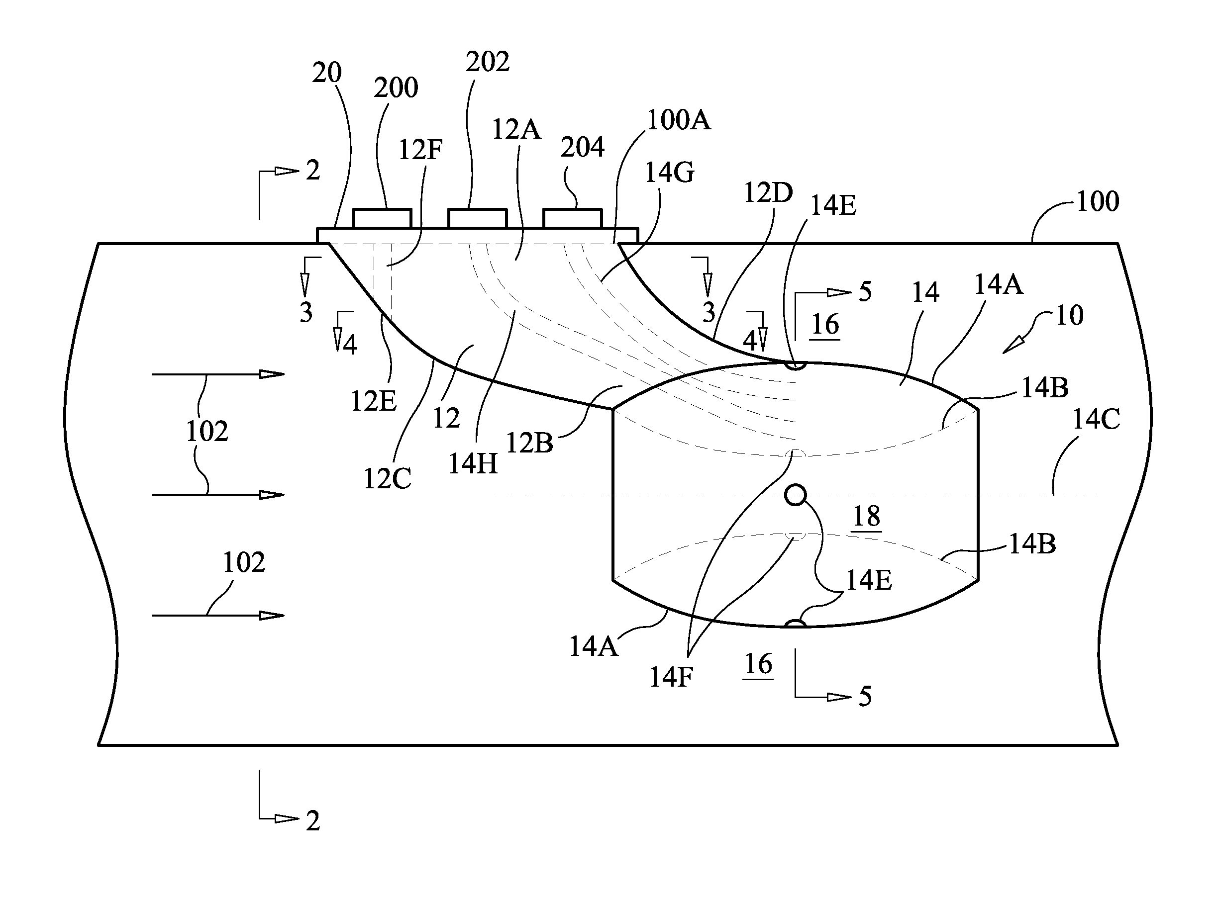
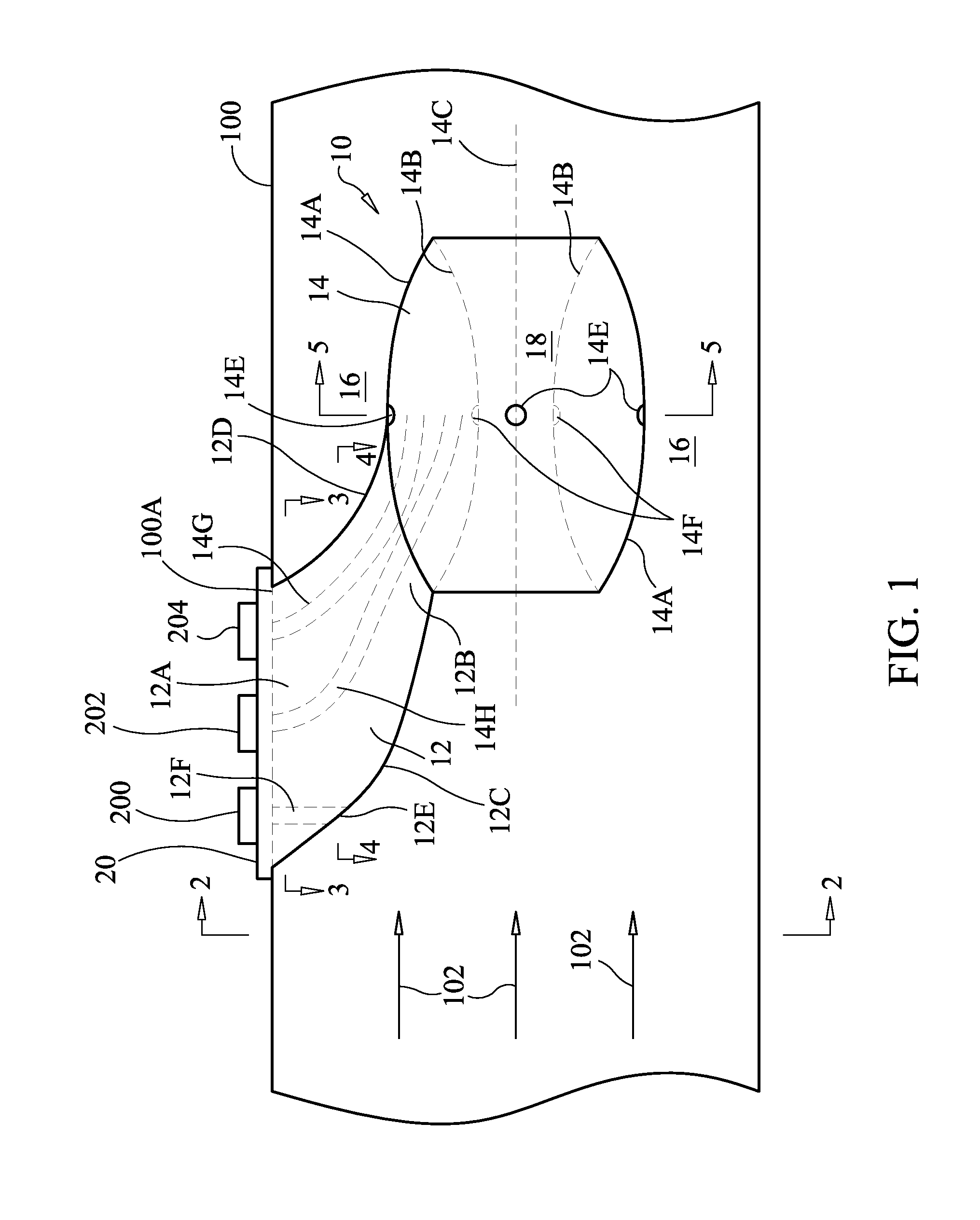
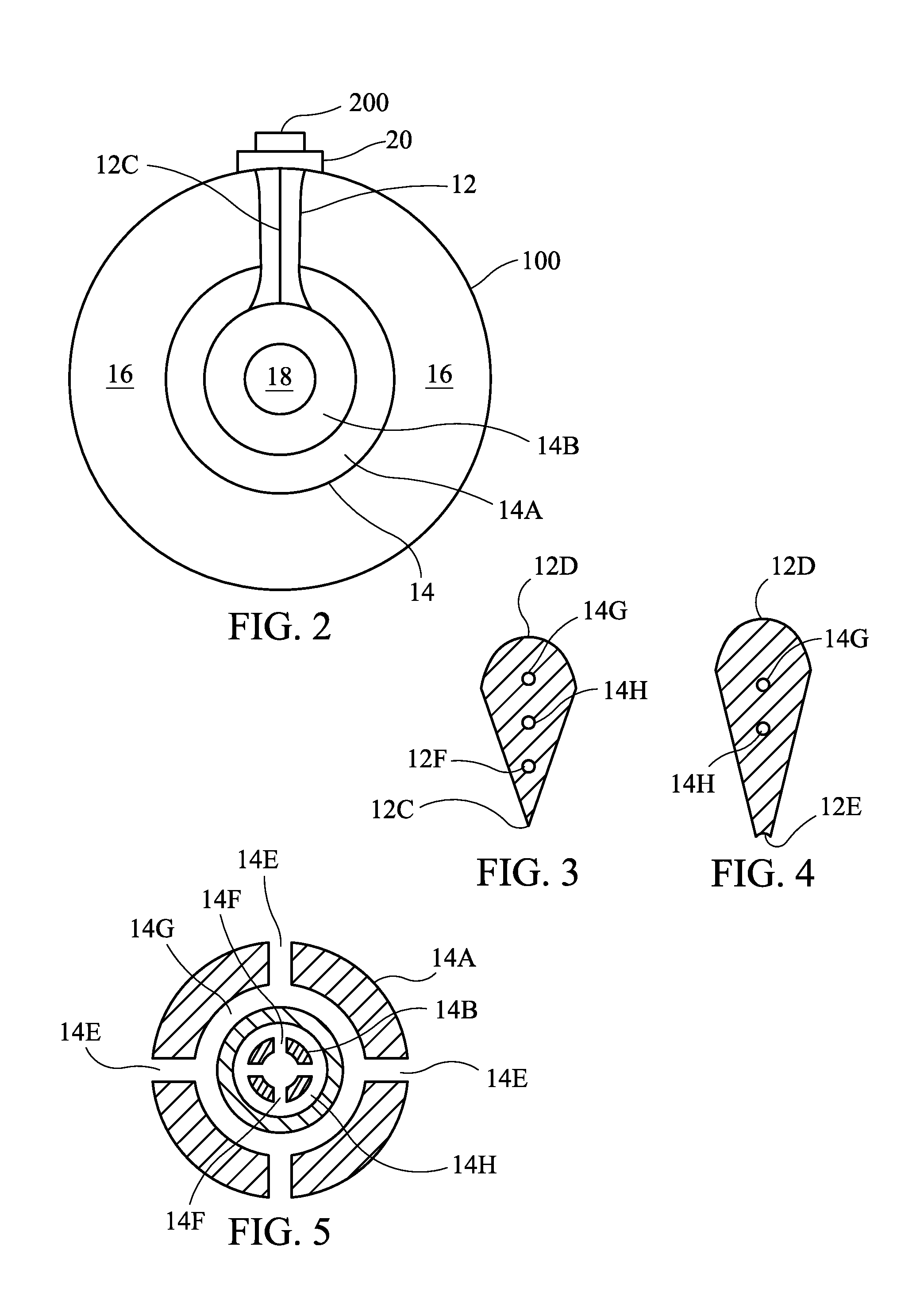
[0019]Referring now to the drawings, simultaneous reference will be made to FIGS. 1-5 where a variety of views of a self-contained device for generating a compressed flow in a conduit to facilitate the collection of differential measurements in accordance with an embodiment of the present invention is shown and is referenced generally by numeral 10. Device 10 is positioned / mounted in a conduit 100 that carries a flowing fluid moving in a known direction where such fluid and its flow direction are indicated by arrows 102. The terms “upstream” and “downstream” as used herein are referenced to the flow direction of fluid flow 102. Fluid flow 102 can be a gas, vapor, a pure liquid, or a gas or liquid mixed with some solids that are present by design or by circumstance. For example, fluid flow 102 could contain natural or man-made debris that must pass through conduit 100 and past device 10 to maintain flow efficiency.

[0020]In general, device 10 is a self-contained device that positions...


PUM


Abstract

A device used in making differential measurements of a flow includes an open-ended tubular flow obstruction and a support arm. The flow obstruction has an outer annular wall and an inner annular wall. The support arm has a first end coupled to an exterior wall of a conduit and a second end coupled to the flow obstruction. The support arm positions the flow obstruction in the conduit such that a first flow region is defined around the flow obstruction's outer annular wall and a second flow region is defined by the flow obstruction's inner annular wall. The support arm's first end and second end are separated from one another with respect to a length dimension of the conduit. Measurement ports provided in the flow obstruction are coupled to points at the exterior wall of the conduit by manifolds extending through the flow obstruction and support arm.

Description

ORIGIN OF THE INVENTION[0001]The invention described herein was made in part by employees of the United States Government and may be manufactured and used by or for the Government of the United States of America for governmental purposes without the payment of any royalties thereon or therefor.CROSS-REFERENCE TO RELATED PATENT APPLICATIONS[0002]This patent application is co-pending with one related patent application entitled “SELF-CONTAINED COMPRESSED-FLOW GENERATION DEVICE FOR USE IN MAKING DIFFERENTIAL MEASUREMENTS”, filed by the same inventors and owned by the same assignee as this patent application.BACKGROUND OF THE INVENTION[0003]1. Field of the Invention[0004]This invention relates to flow measurement tools. More specifically, the invention is a self-contained device that generates compressed flow in a conduit for use in making differential measurements in a flow.[0005]2. Description of the Related Art[0006]For a variety of reasons, devices are needed that can be adapted to ...

Claims


Application Information

Patent Timeline
IPC IPC(8): G01F1/34
CPCG01F1/40
Inventor ENGLAND, JOHN DWIGHTKELLEY, ANTHONY R.CRONISE, RAYMOND J.
Owner NASA
Why Eureka
Try Eureka