Apparatus for moving earth boring machines

Inactive Publication Date: 2003-11-25
HAMPTON RICHARD
View PDF17 Cites 0 Cited by
  • Summary
  • Abstract
  • Description
  • Claims
  • Application Information

AI Technical Summary

Benefits of technology

The present invention relates to apparatus for moving an earth boring machine along a track which can readily be installed in modular form on the machine. The module also can readily be removed for maintenance or other purposes. The apparatus can be retrofitted to existing machines with very little structural modification or effort.
In addition, the apparatus incorporates an arrangement for driving first and second track engagement wheels employed therein which evens out the forces applied to the wheels by a hydraulic motor associated therewith. By evening out the load, the lives of bushings and other components of the system are extended.

Problems solved by technology

Because horizontal earth boring machines are quite heavy, tremendous stresses can be placed on the retraction cables and related equipment, creating a potentially dangerous situation.
This results in uneven forces or loads being applied to the wheels, a factor which lowers the efficiency of the system and promotes wear.
The Fast Trac system is completely disposed within the horizontal earth boring machine to which it is attached and is not readily accessible from outside the machine without partially dismantling the machine.
Both of these factors make access to the system, for example to replace bushings, wheels, or other system parts, very difficult and time consuming.

Method used


Image

  • Apparatus for moving earth boring machines
  • Apparatus for moving earth boring machines
  • Apparatus for moving earth boring machines

Examples


Embodiment Construction

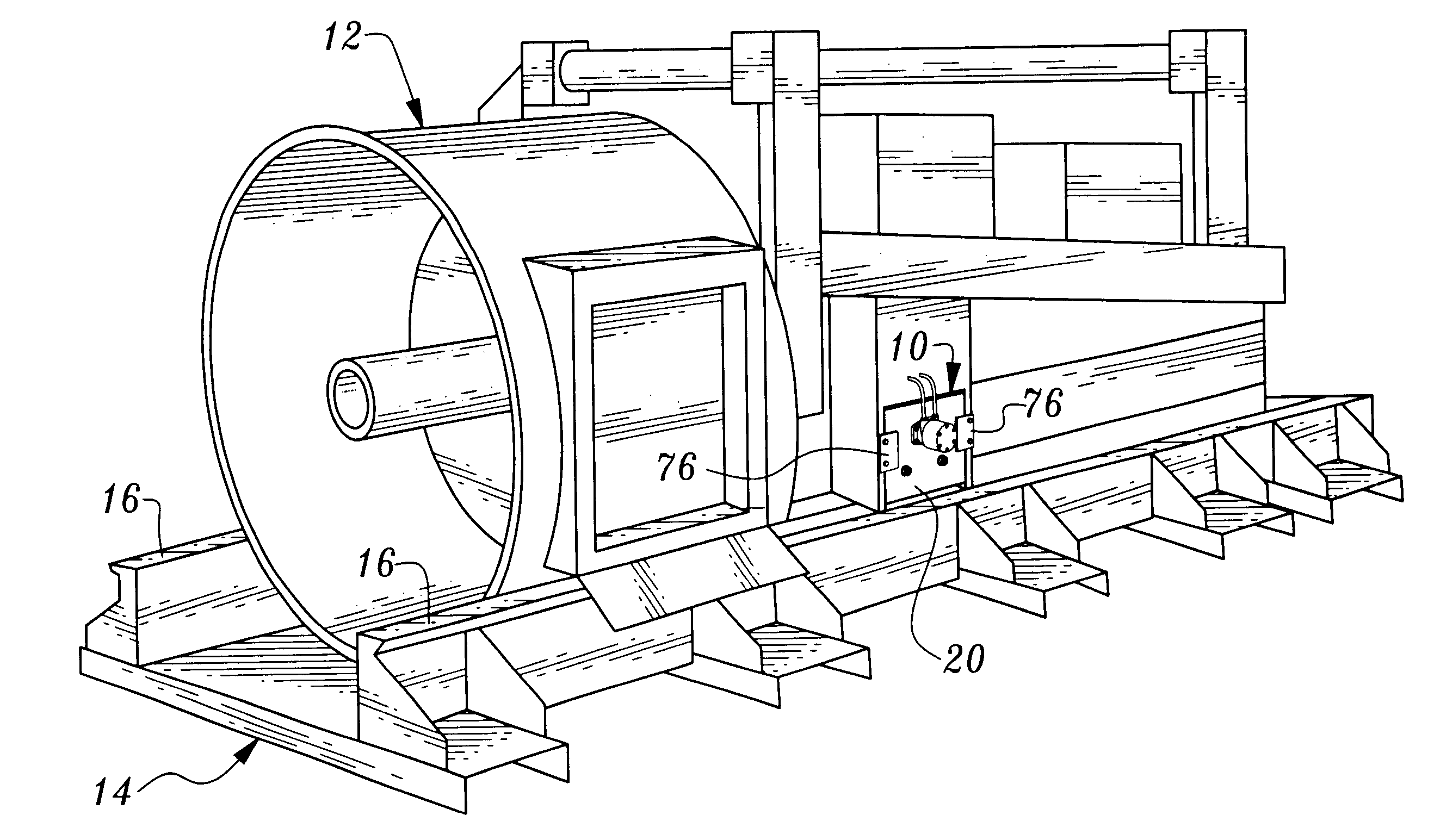
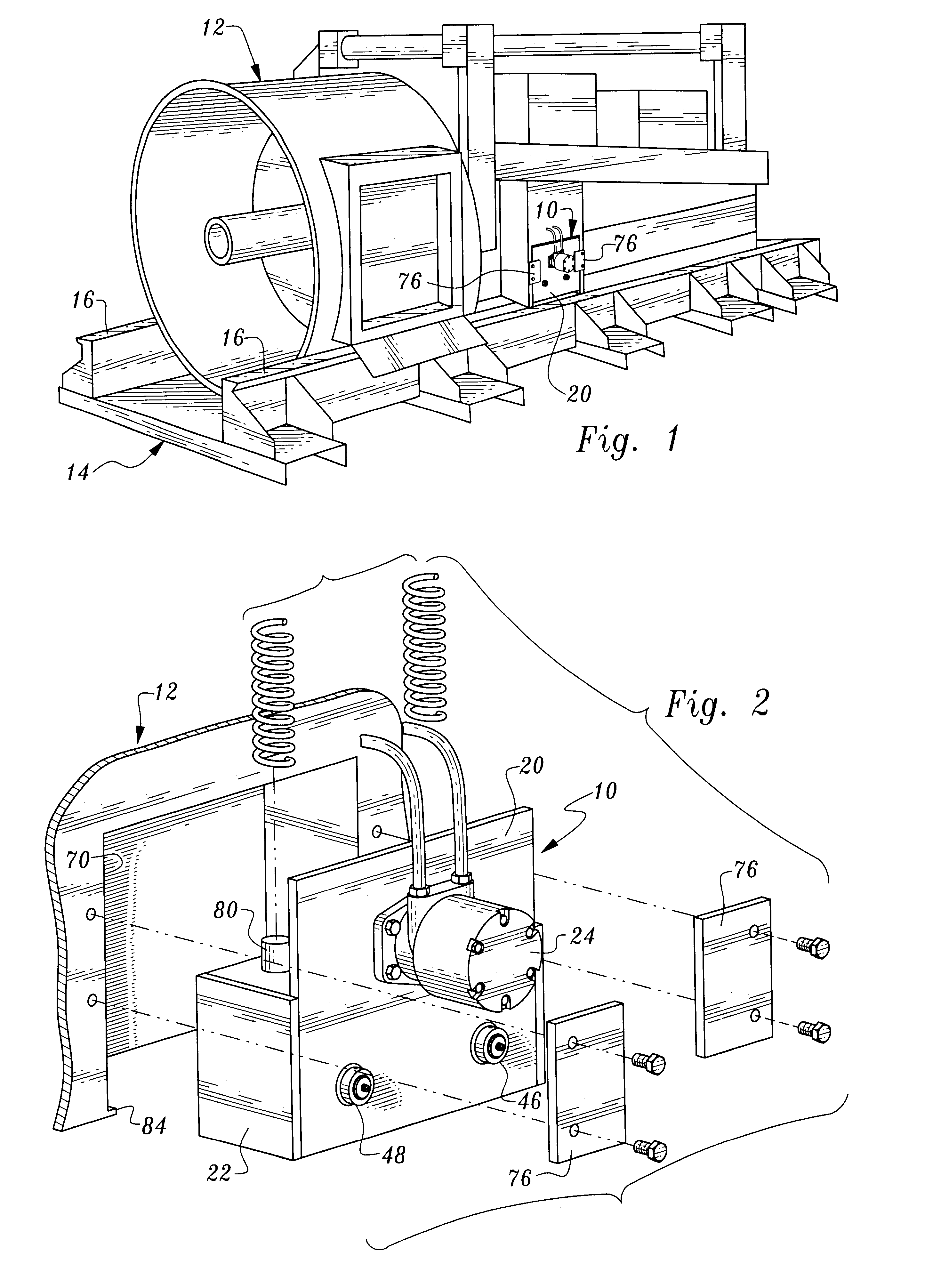
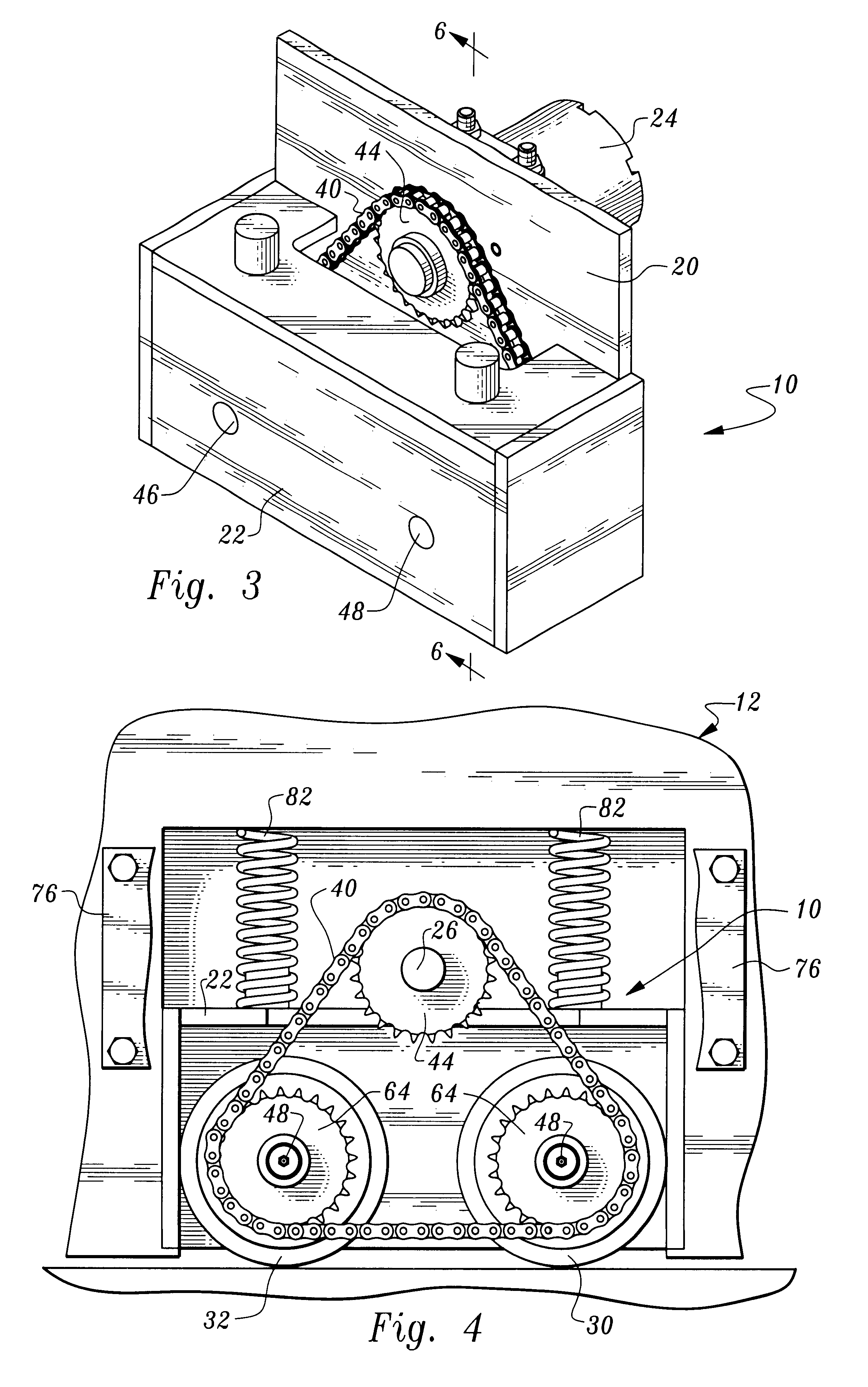
Referring now to FIGS. 1-6, apparatus constructed in accordance with the teachings of the present invention is designated by reference numeral 10. Shown in its entirety in FIG. 1 is a horizontal earth boring machine 12 with which the apparatus is associated. Disposed under earth boring machine 12 is a track way 14 including two tracks 16 disposed side-by-side. Such track ways are conventional and the illustrated horizontal earth boring machine is also of a conventional nature and will not be described in detail.

An example of such a machine is the American Augers Model 36-340 boring machine; however, it is to be appreciated that the apparatus of the present invention may be suitably employed with any horizontal earth boring machine. Of course, an apparatus 10 is deployed on each side of the machine, each apparatus being associated with one of the tracks 16. Since the apparatus 10 is the same on both sides of the machine, only one such unit will be described in detail.

The apparatus of...


PUM


Abstract

Apparatus for moving an earth boring machine along a track includes a module which is releasably connected as a unit to the earth boring machine. The module includes a support plate releasably connected to the earth boring machine.

Description

This invention relates to apparatus for transporting horizontal earth boring machines along track ways.Horizontal earth boring machines are utilized to bore holes or tunnels in the earth for a wide variety of purposes. Such machines are normally moved along and on track ways during the boring operation. It is necessary to periodically move the machines from the front to the rear of the bore pit, for example to install another section of casing or to remove augers from the casing.Retraction cables associated with winches have often been utilized for such purpose. Because horizontal earth boring machines are quite heavy, tremendous stresses can be placed on the retraction cables and related equipment, creating a potentially dangerous situation.A relatively recent development has been the use of motor driven wheels in association with the earth boring machine which engage the track way and are utilized to transport the machine in a direction away from the bore. In particular, a retract...

Claims


Application Information

Patent Timeline
IPC IPC(8): E21B7/04
CPCE21B7/046
Inventor HAMPTON, RICHARD
Owner HAMPTON RICHARD
Why Eureka
Try Eureka