Method and apparatus for dampening waves in a wave pool

a wave pool and wave technology, applied in the field of wave pools, can solve the problems of reducing the “surfable” quality, increasing the attendant risks, and requiring participants to perform surfing maneuvers thereon, so as to reduce the detrimental increase the size of the pool or the risk of the floor design, and reduce the effect of harmful wave reflection and rip curren

Active Publication Date: 2013-10-22
LOCHTEFELD THOMAS J +2
View PDF17 Cites 14 Cited by
  • Summary
  • Abstract
  • Description
  • Claims
  • Application Information

AI Technical Summary

Benefits of technology

[0011]The present invention represents an improvement over previous wave pool designs insofar as it comprises a method and apparatus for reducing detrimental wave reflections and rip currents within a wave pool by providing a wave dampening chamber preferably downstream from the breaker line that absorbs wave energy and dampens waves, wherein larger surfable quality waves can be produced within the wave pool at greater frequencies without increasing pool size or floor design hazard.
[0012]The present invention preferably comprises a wave pool with a wave generator and an obliquely oriented sloped floor that creates waves that begin to break at or near the breaker line, wherein one of the improvements provided by the present invention is a wave dampening chamber that is preferably located downstream from the breaker line, wherein the chamber preferably comprises a relatively shallow raised or “false” perforated floor extending above a relatively deep solid chamber floor, wherein the combination of the raised floor over the solid floor and the porosity of the raised floor help to cause the wave energy to be absorbed and waves to be dampened.
[0015]One improvement provided by the present invention is the inclusion of a wave dampening chamber that is situated downstream from the inclined section, i.e., in the downstream portion of the wave pool. The wave dampening chamber preferably comprises a relatively shallow raised or “false” perforated floor that extends above a relatively deep solid chamber floor. The raised floor is preferably provided with multiple openings, or perforations, that allow a predetermined amount of water and wave energy to pass through—both up and down and through the openings—wherein the rate at which the water is allowed to pass through the raised floor in both directions is determined by its “porosity,” i.e., the perforated area divided by the solid area of the raised floor. By virtue of the raised floor's porosity, and the depth of the raised floor relative to the depth of the solid floor underneath, and taking into account the height of the waves, as well as other wave characteristics and factors, the wave energy can be absorbed and dampened to a significant degree, wherein a boundary layer of energy absorbing vortices and eddies can be created both above and below the raised floor, which help to significantly reduce and eventually dissipate the oncoming waves. This in turn helps to eliminate the amount and severity of rip currents and wave reflections that can otherwise occur within the wave pool, which in turn, helps to allow the next oncoming waves to form and break properly without interference.
[0016]The wave pool of the present invention is, in some ways, constructed much like a conventional wave pool with a wave generator provided at the deep end, and a sloped floor that extends upward toward the shallow end. The wave generator in such case is preferably a conventional type that generates periodic waves that travel across the body of water from the deep end toward the shallow end, wherein the inclined floor acts upon the waves and causes the waves to flow up and build up momentum until the waves curl forward and begin to break. But instead of allowing the waves to break onto a beach or reef as in past wave pools, the inclined floor of the present invention is preferably terminated at or near the break depth, i.e., along the breaker line, and preferably, downstream from the inclined section, a wave dampening chamber is provided to help dampen and dissipate the waves, and eliminate or reduce the rip currents and adverse wave reflections that can otherwise form in the wave pool. Even with an end wall at the far end, which in an ordinary wave pool can cause unwanted wave reflections to occur, the wave dampening chamber of the present invention preferably dampens and dissipates the waves and the wave energy such that there are few if any adverse movements remaining in the waves by the time the next oncoming waves approach and are acted upon by the sloped incline.
[0017]In one aspect, the present invention represents an improvement over previous wave pool designs in that the wave dampening chamber preferably comprises a specially designed raised perforated floor that helps to absorb wave energy and therefore reduce the height of the waves (after they begin to break) and eventually dissipate so that by the time the next oncoming waves approach, the rip currents and wave reflections that could otherwise interfere with the oncoming waves are substantially diminished or non-existent. This enables the surf zone of the wave pool (upstream of the breaker line where the waves ultimately break) to be relatively free of unwanted motions, including rip currents and wave reflections, thereby helping to produce larger and better quality surfing waves at greater frequencies, and thereby, to increase throughput without increasing pool size. While in traditional wave pools, energy from a wave breaking onto the beach normally creates white water and mass transport onto the beach, the after-break zone of the present invention dampens and dissipates the waves, such that rip currents and wave reflections that normally occur in and around the surf zone are substantially reduced, and such that larger surfable quality waves can be produced at greater frequencies.
[0025]Accordingly, in each case, there is preferably a ratio or range that provides the best dampening rate possible relative to the depth of the chamber floor and the expense needed to construct the pool with a depth of that magnitude.

Problems solved by technology

First, due to the increase in the size of the waves, there is the concomitant increase in the occurrence of rip currents which can reduce the “surfable” quality of the waves, and consequently, make it more difficult for participants to perform surfing maneuvers thereon.
They can also increase the attendant risks.
These “rip currents” tend to flow against the oncoming waves and can detrimentally affect how water and wave energy dissipate.
A second related disadvantage of the cross-over wave pool is that wave reflections that are similar to those that exist in nature can occur.
For example, wave reflections typically occur when there is an end wall at the far end of the pool, or a relatively steep beach or reef, that tends to reflect the wave energy back across the wave pool in a reverse direction, such that, as the waves progress and are reflected back, they can interfere with the next oncoming wave.
On account of such reflections, a backwash can be created, which can lead to a significant decrease in surfable wave quality, which in turn, can make performing surfing maneuvers more difficult
A third corollary disadvantage related to the formation of rip currents and wave reflections is the resultant reduction in the pool's productive asset value that can result from having to reduce the frequency of the waves in an attempt to reduce these unwanted movements and characteristics.
Although it is usually desirable to increase the frequency of wave generation to increase the number of riders that can ride on the waves per hour (with a corresponding increase in revenue per hour using the same asset base), the downside to doing so is that the occurrence of rip currents and wave reflections can thereby increase.
Therefore, an associated disadvantage that can result from the use of large cross over wave pools is that the frequency of wave generation can be reduced, i.e., such as down to one wave every minute to ninety seconds or more, in which case, the asset value of the property is reduced as well.
A fourth disadvantage is that such cross over wave pools tend to be larger and inherently more expensive to build.
This is especially true when wave pools are installed in areas where land is scarce, and therefore, building larger cross-over wave pools, simply to increase wave size is not often very cost effective.
Renovating an existing wave pool to make it larger also requires a significant amount of effort and expense.
A fifth disadvantage to the cross-over wave pool occurs in situations where wave pools are used to host surfing exhibitions and competitions.
As discussed, because of the risks associated with making surfing waves bigger, some effort has been made to build cross-over wave pools that are sufficiently large enough to ‘dilute’ the rip current and wave reflection problems discussed above.
Unfortunately, such a solution has the detrimental effect of forcing spectators (who are normally seated on bleachers or grandstands immediately behind the beach and above the waterline) further away from the waves, which can make it more difficult for them to see and enjoy the wave and surf action.

Method used


Image

  • Method and apparatus for dampening waves in a wave pool
  • Method and apparatus for dampening waves in a wave pool
  • Method and apparatus for dampening waves in a wave pool

Examples


example one

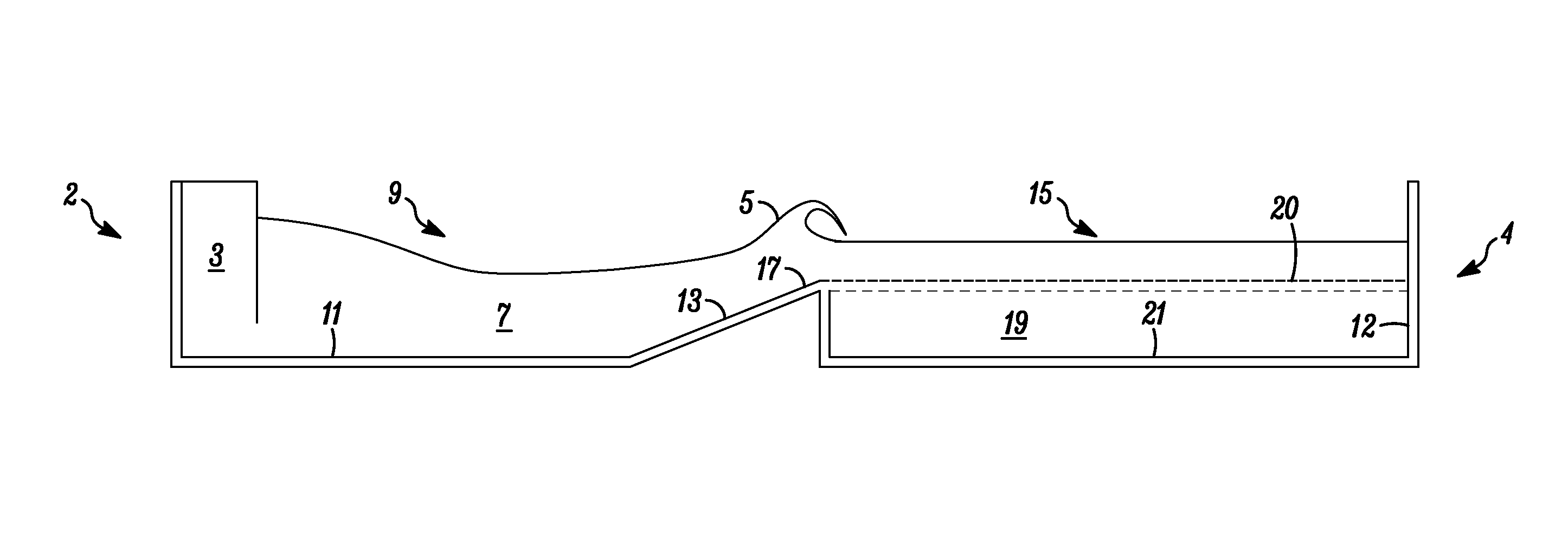
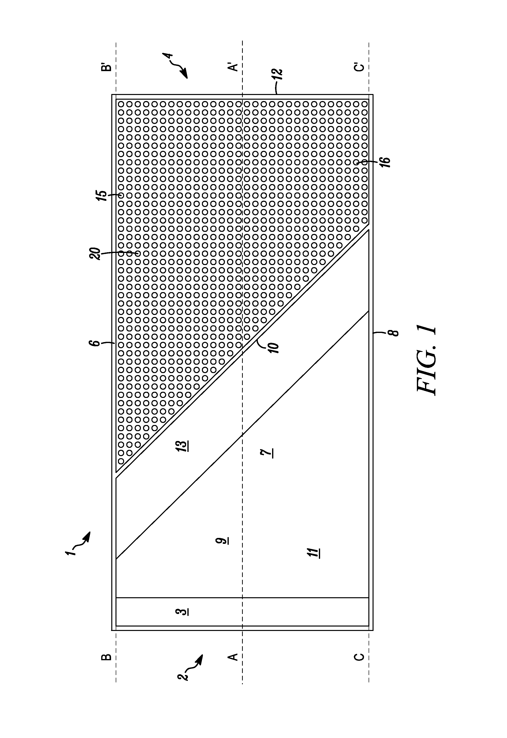
[0097]When it is desirable to produce barrelling waves that range in height from three to eight feet high, with a period of about fifteen seconds, the preferred depth of horizontal floor 11 or Pool depth is typically about three times the wave height. Accordingly, if the desired wave height is three feet, the preferred pool depth would be nine feet deep, and likewise, if the desired wave height is eight feet, the preferred pool depth would be twenty four feet deep. These represent preferred minimum and maximum pool depth values dpool for each circumstance.

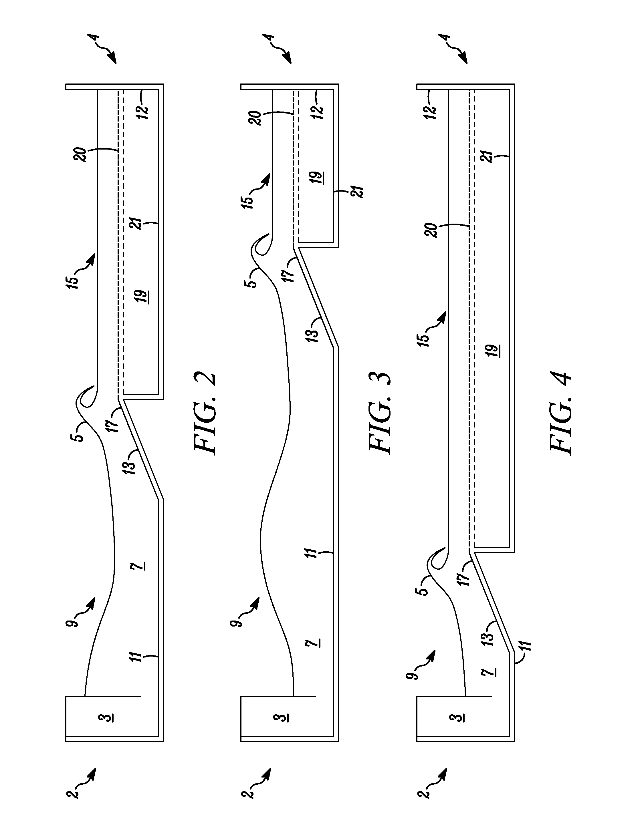
[0098]The preferred slope of inclined section 13 to create barrelling type waves, having a fifteen second period, is preferably between about 5% and 10%, which is the slope that extends up from horizontal floor 11. At the same time, inclined section 13 preferably terminates at the breaker depth, and raised floor 20 is preferably extended substantially horizontally from inclined section 13 toward end wall 12 at that same depth. In t...

example two

[0101]When it is desirable to produce spilling waves that range in height from three to eight feet, with a period of about eight seconds, the preferred depth of horizontal floor 11 or Pool depth is typically about three times the wave height. Accordingly, if the desired wave height is three feet, the preferred pool depth would be nine feet. Likewise, if the desired wave height is eight feet, the preferred pool depth would be twenty four feet. These represent the preferred minimum and maximum pool depth values dpool for each circumstance. And, to create spilling type waves, the preferred slope of inclined section 13 is preferably at or below 5%, which is the slope that extends up from horizontal floor 11. At the same time, as discussed previously, inclined section 13 preferably terminates at the breaker depth, wherein the top 17 of inclined section 13 and raised floor 20 would also be located at the same depth.

[0102]In this example, based on the above factors, the preferred breaker d...

example three

[0105]In another example, when it is desirable to produce barrelling waves that are five feet high, having a period of fifteen seconds, in a wave pool having a horizontal floor 11 that is fifteen feet deep, the following applies:

[0106]The slope of inclined section 13 is preferably about 10% to enable barrelling type waves to be produced. And, in this example, based on the above factors, the preferred breaker depth is determined to be about three feet. Accordingly, in this example, with the wave height being five feet, and the preferred pool depth being about fifteen feet, the preferred submerged depth of raised floor 20 would be about three feet. Note that if this value is much greater than three feet, the waves won't break properly, and if this value is much less than three feet, there is the risk of backwash occurring.

[0107]It has also been determined that the preferred depth of wave dampening chamber 19 beneath raised floor 20 is about three times the depth of raised floor 20, or...


PUM


Abstract

A wave pool for producing periodic waves preferably having a first wave forming portion with an inclined section oriented obliquely relative to the travel direction of the waves, and a second wave dampening portion having a relatively deep solid chamber floor and a raised perforated floor above it for dampening the waves. The wave dampening portion preferably dissipates the waves, which in turn, reduces wave reflections and rip currents that can otherwise interfere with the oncoming waves.

Description

RELATED APPLICATION[0001]This application claims priority from U.S. provisional application Ser. No. 61 / 200,183, filed Nov. 25, 2008.FIELD OF THE INVENTION[0002]The present invention relates to the field of wave pools, and in particular, to a wave pool that generates large surfing class waves that are dampened to enable increased throughput per available unit of space.BACKGROUND OF THE INVENTION[0003]Wave pools have become popular at water theme parks in recent years. Wave pools are man-made bodies of water in which waves are created much like waves in an ocean. A wave pool typically has a wave generating machine located at one end and an artificial sloped “beach” located at the other end, wherein the wave generating machine creates periodic waves that travel from that end to the other end. The floor of the pool near the beach end is preferably sloped upward so that as the waves approach, the sloped floor causes the waves to “break” onto the beach.[0004]In some cases, the size and p...

Claims


Application Information

Patent Timeline
Patent Type & Authority Patents(United States)
IPC IPC(8): A47K3/10
CPCE04H4/0006A63B69/0093Y02E10/30
Inventor LOCHTEFELD, THOMAS J.VAN ETTINGER, HENDRIK DIRKBASTENHOF, DIRK
Owner LOCHTEFELD THOMAS J
Why Eureka
Try Eureka