
Vehicle headlamp apparatus and control method thereof

a headlamp and headlamp technology, applied in the field of headlamps, can solve the problems of increased size and cost of actuators, excessive stress on the light source of infrared projectors,

Inactive Publication Date: 2013-10-22
KOITO MFG CO LTD
View PDF15 Cites 2 Cited by
  • Summary
  • Abstract
  • Description
  • Claims
  • Application Information

AI Technical Summary

Benefits of technology

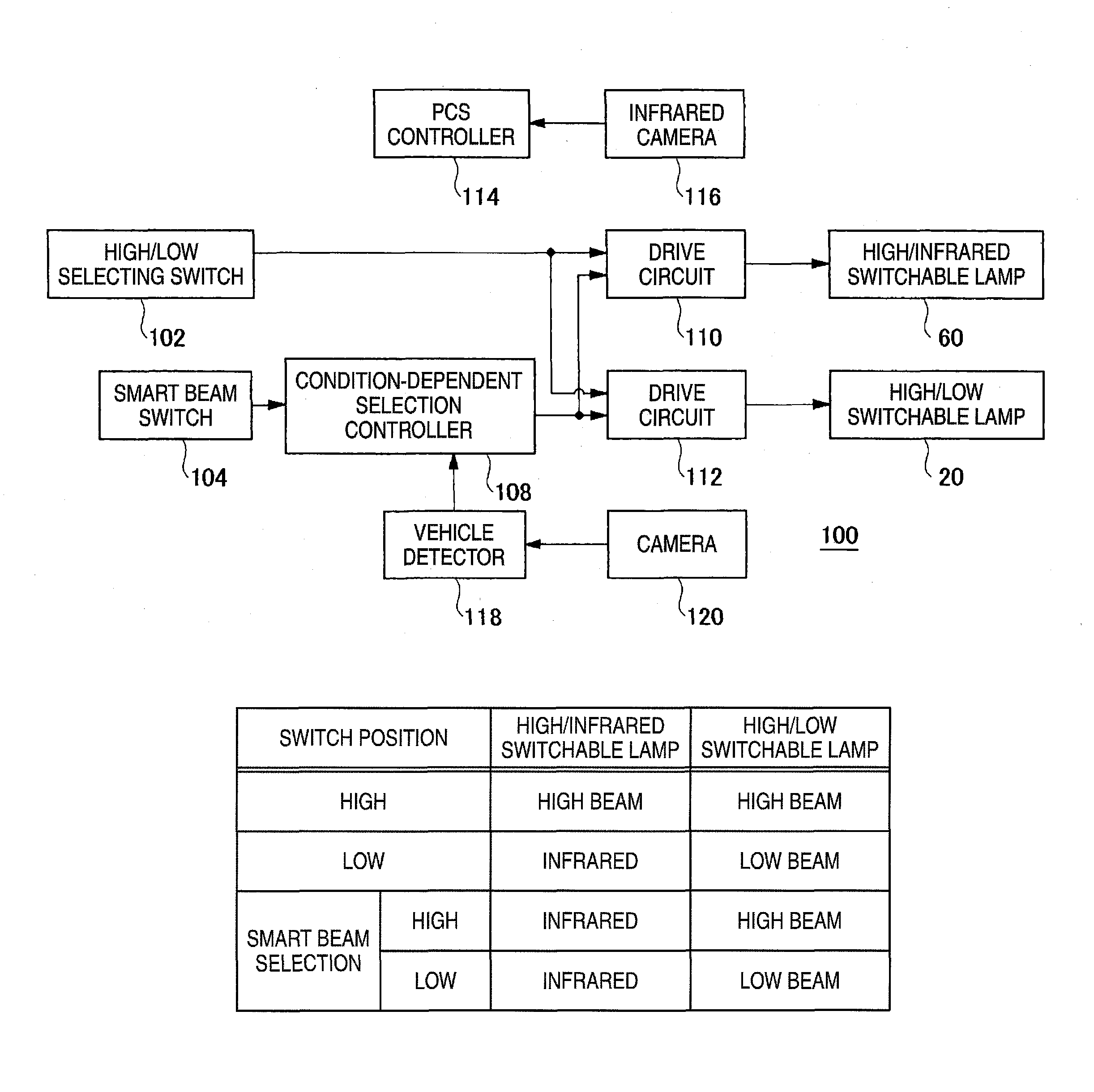
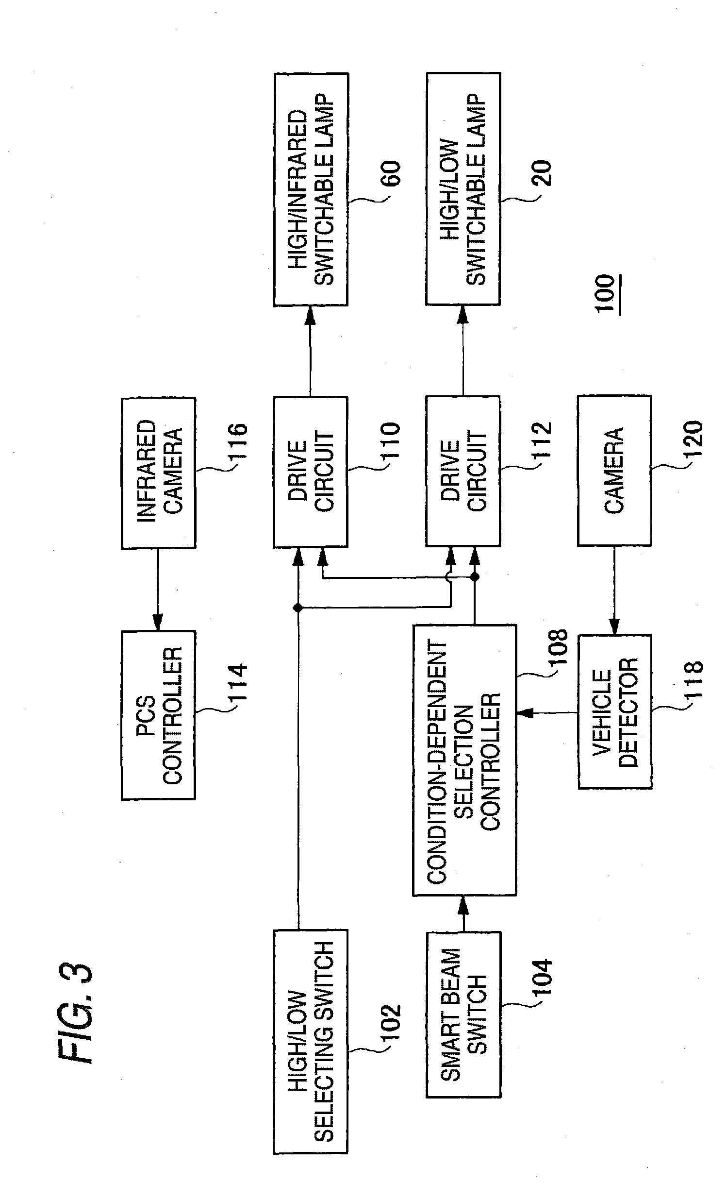
The present invention provides a vehicle headlamp apparatus that includes two lamps, a vehicle detector, and a condition-dependent selection controller. The controller controls the second lamp to produce a low beam light distribution pattern when the vehicle detector detects a vehicle, and to produce a second high beam light distribution pattern when the vehicle detector detects no vehicle. The controller also controls the first lamp to produce an infrared light distribution pattern, regardless of whether the vehicle detector detects any vehicle. The technical effect of this invention is to provide a vehicle headlamp apparatus that can automatically adjust its light distribution pattern based on the vehicle's speed and presence, improving safety and visibility for drivers.

Problems solved by technology

However, in this related art, the infrared projector may be frequently turned on and off in which case a light source of the infrared projector undergoes excessive stress.
Thus, a size and cost of the actuator will be increased.

Method used


Image

  • Vehicle headlamp apparatus and control method thereof
  • Vehicle headlamp apparatus and control method thereof
  • Vehicle headlamp apparatus and control method thereof

Examples


first exemplary embodiment

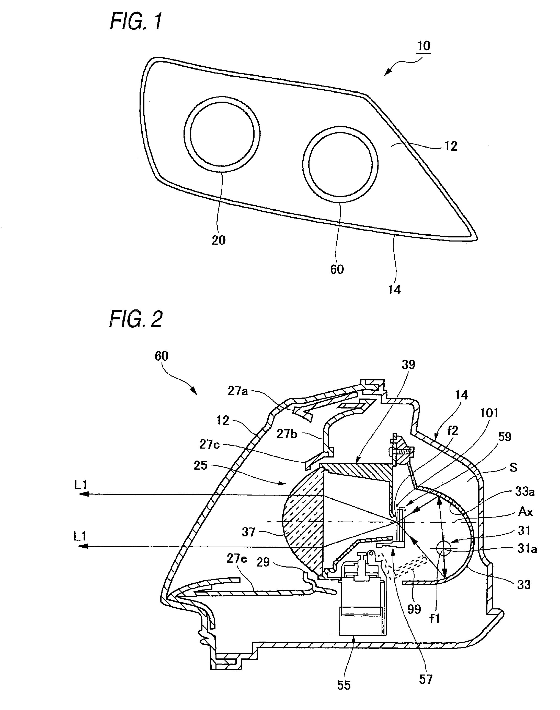
[0022]FIG. 1 is a front view of a vehicle headlamp 10 according to the first exemplary embodiment. The headlamp 10 of FIG. 1 is mounted on a right side (a left side when viewed from the front of the vehicle) of a front part of the vehicle. The vehicle headlamp 10 has a transparent cover 12 and a lamp body 14. The lamp body 14 may be made of synthetic-resin, and has a front opening to which the transparent cover 12 is attached. Inside a lamp chamber S surrounded by the transparent cover 12 and the lamp body 14 (see FIG. 2), a high / infrared switchable lamp 60 (a first lamp) and a high / low switchable lamp 20 (a second lamp) are arranged. Between the high / low switchable lamp 20 and the high / infrared switchable lamp 60, and the transparent cover 12, a plurality of extensions (e.g., extension 27a, 27b, 27c, 27e shown in FIG. 2) are arranged to cover a region surrounding the high / low switchable lamp 20 and the high / infrared switchable lamp 60 when viewed from the front of the headlamp 10.

[...

second exemplary embodiment

[0048]In the first exemplary embodiment, it is when the driver selected the smart beam mode from the smart beam switch 104 that the condition-dependent selection controller 108 controls the high / infrared switchable lamp 60 to produce the infrared light distribution pattern irrespective of whether a vehicle running ahead is detected. In a second exemplary embodiment, instead of the high / low selecting switch 102 and the smart beam switch 104, a mode selection switch is disposed in the passenger compartment. The mode selection switch is manually operable by the driver to select one of a low beam mode, a high beam mode, and a smart beam mode (a condition dependent mode).

[0049]FIG. 8 is a diagram showing a relationship between positions of the mode selection switch and the light distribution patterns to be produced by the high / infrared switchable lamp 60 and the high / low switchable lamp 20. When the mode selection switch is positioned to select the high beam mode, the condition-dependent...


PUM


Abstract

A vehicle headlamp apparatus is provided. The vehicle headlamp apparatus includes a first lamp configured to selectively produce a first high beam light distribution pattern and an infrared light distribution pattern, a second lamp configured to selectively produce a second high beam light distribution pattern and a low beam light distribution pattern, a vehicle detector which detects a vehicle running ahead, and a condition-dependent selection controller which controls the first and second lamps. The condition-dependent selection controller controls the second lamp to produce the low beam light distribution pattern when the vehicle detector detects a vehicle and to produce the second high beam light distribution pattern when the vehicle detector detects no vehicle. The condition-dependent selection controller controls the first lamp to produce the infrared light distribution pattern, irrespective of whether the vehicle detector detects a vehicle.

Description

CROSS-REFERENCE TO RELATED APPLICATION[0001]The present application claims priority from Japanese Patent Application No. 2008-230336 filed on Sep. 8, 2008, the entire content of which is incorporated herein by reference.FIELD OF INVENTION[0002]Apparatuses and methods consistent with the present invention relate to a headlamp which is used in, for example, vehicles.DESCRIPTION OF RELATED ART[0003]Generally, vehicle headlamps are operable to selectively produce a low beam and a high beam. The low beam is used when driving in, for example, urban areas to irradiate a near region. A light distribution pattern of the low beam is regulated so as not to give glare to vehicles running ahead such as oncoming vehicles and preceding vehicles. The high beam is used when driving on, for example, thruways where there are no or few oncoming vehicles and preceding vehicles and irradiates a wider range including a distant region with relatively high illumination intensity.[0004]The high beam provides...

Claims


Application Information

Patent Timeline
Patent Type & Authority Patents(United States)
IPC IPC(8): B60Q1/02H05B37/02B60Q1/14H05B39/04F21V9/00H05B41/36
CPCB60Q1/1423F21S48/1186F21S48/1778B60Q2300/41B60Q2300/42F21S41/689
Inventor SUGIMOTO, ATSUSHIDEGUCHI, HIROHISAYOKOI, SHOICHIROSUGIYAMA, YUJI
Owner KOITO MFG CO LTD
Learn More