
Tunneled datagram switching

Inactive Publication Date: 2006-11-14
CISCO TECH INC
View PDF7 Cites 111 Cited by
  • Summary
  • Abstract
  • Description
  • Claims
  • Application Information

AI Technical Summary

Benefits of technology

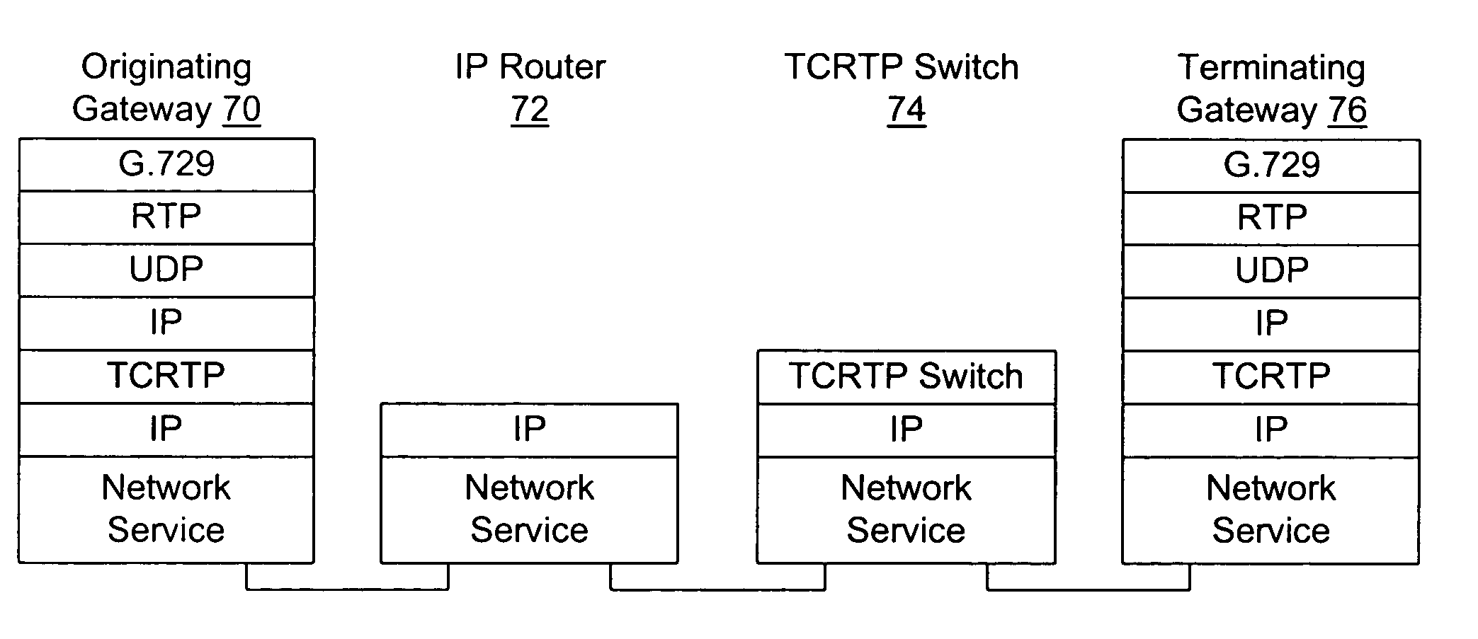
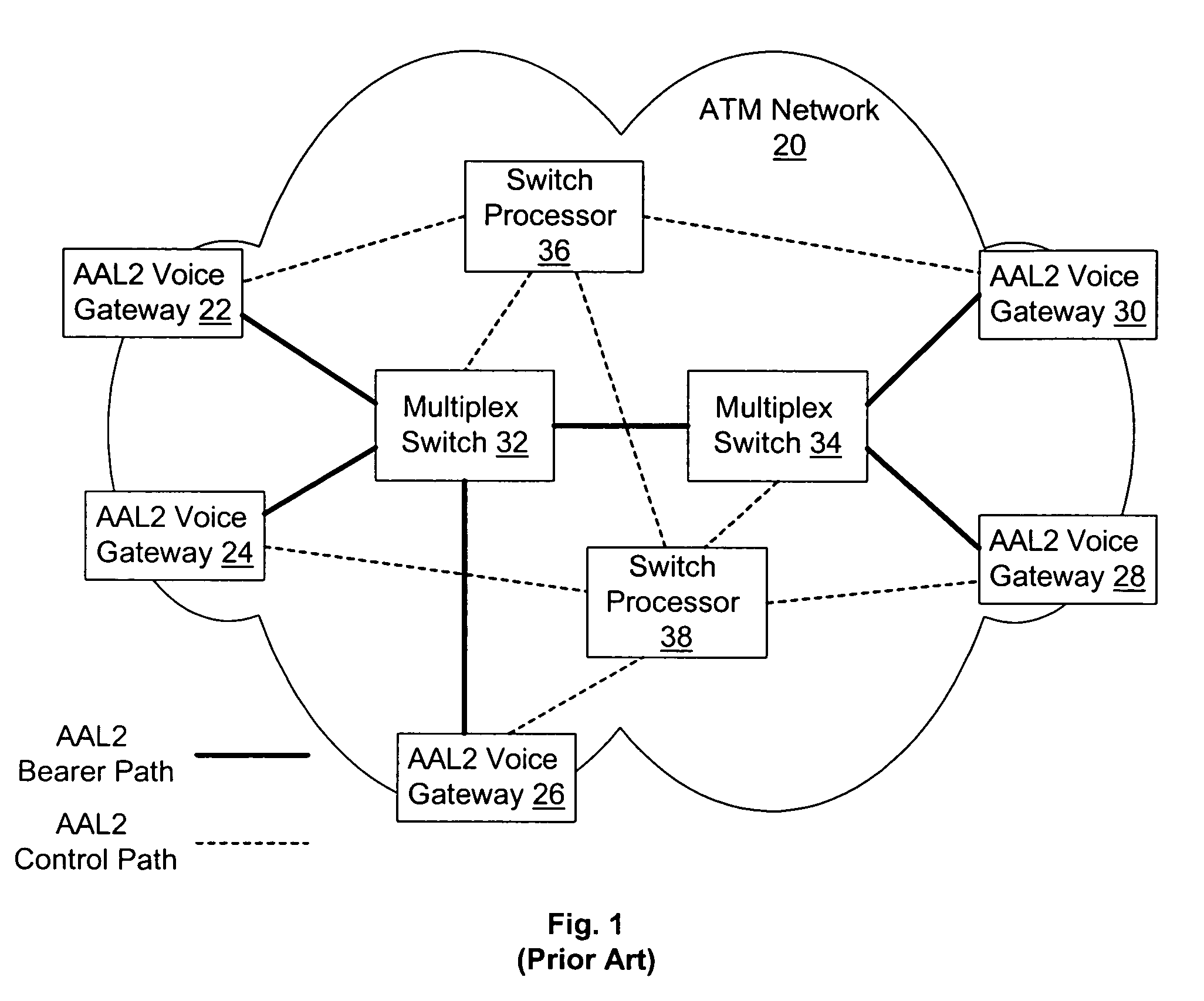
[0017]The preferred embodiments of the invention were designed to retain what is good about AAL-2 trunking (low average bit-rate per voice channel), while adding robustness and scalability at a level not found in the AAL-2 approach. Whereas AAL-2 uses a multiplex that switches on two tags (VPI / VCI, for each AAL-2 trunk, and CID, for each call in a VPI / VCI trunk) at each switching point as instructed by a switch processor, the preferred embodiments use a multiplex that can be switched under local switch control on two datagram headers, one that identifies the trunk, and a second that identifies the destination of each call in the trunk. Preferably, the second header is compressed, and the first header may be compressed on a link basis as well. Although this change in multiplex format may not seem significant in the abstract, it allows a host of significant differences in how a network according to the invention can operate.
[0018]First, call control can be greatly simplified. In preferred embodiments, call agents control call admission only: the call agent does not control core network routing, is not needed to instruct switching points, and is not needed to provide failover capability. These improvements enhance the scalability of the network.
[0019]Second, the preferred embodiments utilize dynamic end-to-end network routing. This allows any switching point in the network to reroute around a failure, without instruction. And because these embodiments can operate in an Internet Protocol (IP) environment, they can leverage the extensive IP routing capabilities already in place. Furthermore, between IP switching points, multiplexed packets produced by these embodiments can be transported efficiently on any underlying network, including ATM.

Problems solved by technology

First, because on a typical TDM link a circuit is dedicated to each call, each voice channel uses all of its allotted time slots, even if the voice data is blank because the speaker is silent.
Second, many voice compression algorithms exist that can significantly reduce the number of bits required to transmit a voice signal with acceptable quality, but circuit-switched TDM is not designed to use these algorithms.
The sampling interval used in packet voice to assemble a complete packet also comes with a disadvantage.
Because no samples from a given sampling interval can be dispatched until the end of the sampling interval, a packet formation delay is introduced in the voice data.
Thus the sampling interval cannot be too long (generally, anything more than a few tens of msec is considered too long), or call quality suffers.
But as the datagram's header(s) may require 40 bytes or more, a great deal of the bandwidth efficiency gained over TDM is lost because of the relatively large header required per packet and the number of small-payload packets that must be sent.
Although methods have been proposed to compress higher-layer headers across a single network link, these methods can place a heavy computational tax on each network element that must deal with the compressed headers, and the efficacy of such methods is highly dependent on the link layer technology employed.
Particularly for core network switches, the sheer number of packets handled on each link make such approaches undesirable.
The cell header is not a true datagram header, however, as it does not contain enough information to allow end-to-end delivery of a cell.
When used with a voice codec such as G.729, ATM, like packet-based voice, may also waste bandwidth—not because ATM cell headers are excessively long, but because the cell payload is fixed at 48 bytes.
Despite the efficient transport capabilities of the ATM / AAL2 voice network, it does have its disadvantages.
As the network scales, these tasks become more and more difficult for the switch processors to perform well.

Method used


Image

  • Tunneled datagram switching
  • Tunneled datagram switching
  • Tunneled datagram switching

Examples


Embodiment Construction

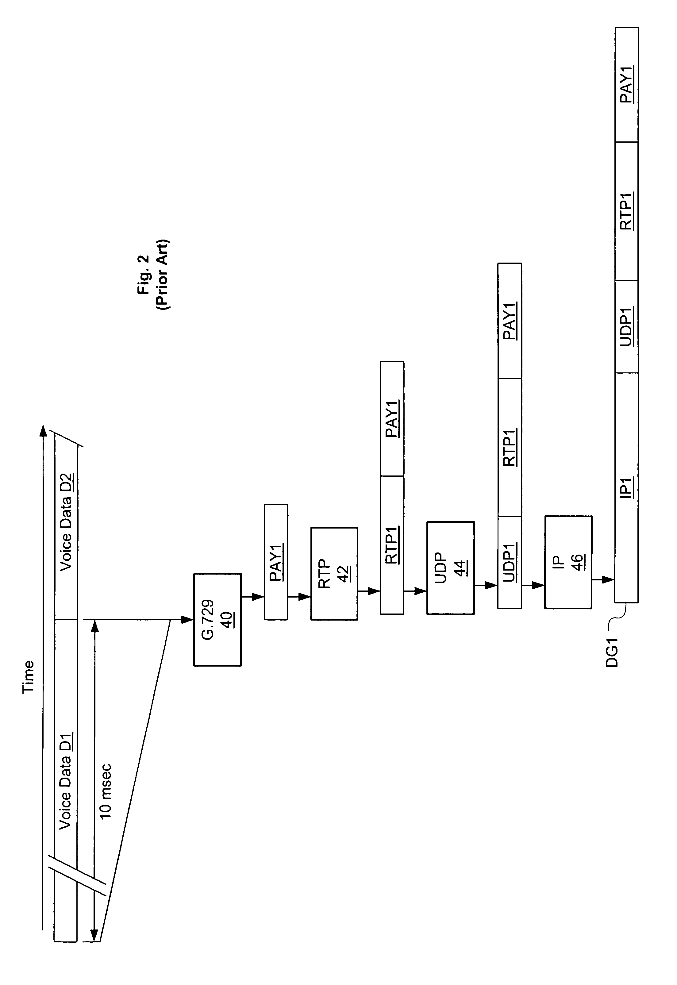
[0033]The preferred embodiments are described below in the context of one of many known methods for creating packet voice data payloads, as depicted in FIG. 2. This method entails using Voice Activity Detection (VAD) to suppress packet generation during quiet times (a silence packet may be sent to indicate that the voice decoder should insert comfort noise in its output during these intervals). When voice activity is present, digitized audio is compressed for fixed time slices (e.g., 10 msec) using a coder such as the G.729 coder. FIG. 2 shows G.729 coder 40 gathering 10 msec of digitized voice data D1, and compressing D1 to create a compressed voice payload PAY1. Assuming voice activity is present during the next 10 msec, at the end of that period voice data D2 will be compressed likewise.

[0034]Compressed packet voice payloads are next encapsulated using the Real-time Transport Protocol (RTP), as described in H. Schulzrinne et al., “RTP: A Transport Protocol for Real-Time Applicati...


PUM


Abstract

A method for transporting real-time data such as voice over a packet-based infrastructure, and a switch for use with that method, are disclosed. In this method, datagrams from multiple data streams are packaged in a single tunnel packet for transport across a network to an intermediate switching point (switch). To reduce bandwidth, each datagram in the tunnel packet (e.g., tunneled datagram) can be sent in a compressed-header format identified by a context identifier (CID) for its data stream. The switch saves context state for each tunnel and CID it is receiving packets for. The switch deaggregates received tunnel packets into tunneled datagrams and associates each datagram with its context state. Based on the destination indicated in its context state, each datagram it re-aggregated in an outgoing tunnel packet bound for a next switch or the destination endpoint itself.

Description

FIELD OF THE INVENTION[0001]This invention pertains generally to packet switching of voice and similar isochronous data, and more particularly to methods and apparatus for switching tunneled datagrams within a wide-area network (WAN).BACKGROUND OF THE INVENTION[0002]“Voice data” generally refers to data that has been created by sensing and digitizing human-audible sounds, and is a primary source of data for telephone networks. Traditionally, voice data has been transmitted over the Public Switched Telephone Network (PSTN) using 8,000 digital audio samples per second, eight bits / sample. This means that one-way voice communication on the PSTN requires 64 kbits / second of network bandwidth. In the traditional scheme, TDM (Time Division Multiplexing) has been used to carry more than one voice channel on a network link, e.g., by dividing a higher bit-rate channel into frames comprising multiple “time slots”, and assigning each voice channel to a certain time slot in each frame.[0003]Circu...

Claims


Application Information

Patent Timeline
IPC IPC(8): H04L12/66H04J3/24H04L12/28
CPCH04L12/4633H04L29/06027H04L65/605H04L65/607H04L65/765H04L65/70H04L65/1101
Inventor TWEEDLY, ALEXTHOMPSON, BRUCE
Owner CISCO TECH INC
Learn More