Method and system to detect respiratory asynchrony

a technology of respiratory asynchrony and detection method, which is applied in the field of respiratory asynchrony detection method and system, can solve the problems of poor synchronized patients, poor patient safety, and inability to detect respiratory muscle fatigue, and achieves the obvious disadvantage of being invasive and not well tolerated by many patients

Active Publication Date: 2013-11-05
RESPIVAR LLC
View PDF8 Cites 9 Cited by
  • Summary
  • Abstract
  • Description
  • Claims
  • Application Information

AI Technical Summary

Benefits of technology

[0012]It is a further object of the present invention to provide a method and system to detect respiratory asynchrony that does not require considerable operator experience.
[0013]It is still a further object of the present invention to provide a method and system to detect respiratory asynchrony that allows appropriate, non-asynchronous ventilatory support.

Problems solved by technology

Poorly synchronized patients may develop respiratory muscle fatigue, remain on mechanical ventilation longer and appear to have worse outcomes.
Appropriate ventilatory support depends to a great extent on the reliable recognition of ventilator asynchrony; however, this is not a simple task.
Both methods have the obvious disadvantage of being invasive and not well tolerated by many patients, in particular those who are alert and awake.
Further, they are relatively complex and require considerable operator experience.
Although useful as a research tool, the AI method is not easily applied to monitoring patient-ventilator asynchrony since it is laborious and operator dependent.
This method has the disadvantage of detecting only one type of patient-ventilator interaction.
Aliasing of the airway signal with background noise may interfere with the ability of some of these methods to distinguish small deflections indicative of wasted inspiratory effort.
Moreover, they may fail to identify conditions in which ventilatory support during inspiration is not sufficient to meet ventilatory requirements.
Although apparently synchronous, this situation results in increased work of breathing from patient generated negative pressure efforts.

Method used


Image

  • Method and system to detect respiratory asynchrony
  • Method and system to detect respiratory asynchrony
  • Method and system to detect respiratory asynchrony

Examples


Embodiment Construction

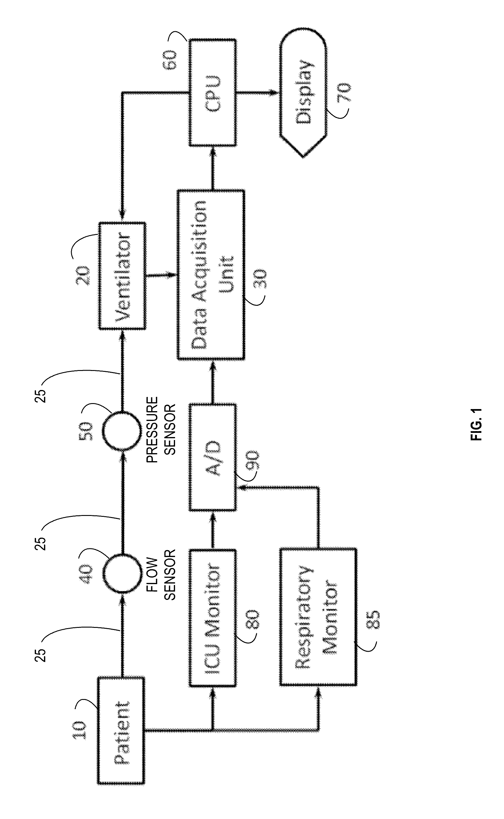
[0025]FIG. 1 is a schematic block diagram of an embodiment of a system for detecting respiratory asynchrony in accordance with the present invention. Referring to FIG. 1, in an exemplary embodiment, a patient 10 is coupled to a ventilator 20 via, for example, one or more flexible tubes or hoses 25 (not shown, but represented by the logical arrows between elements 10, 40, 50, and 20. A data acquisition system 30 acquires data such as air flow data from air flow sensor 40, air pressure d.ata from pressure sensor 50, and / or data from any other data source (e.g., sensor) such as respiratory monitor 85, or optional intensive care unit 80. Preferably such other data sources or sensors are capable of sensing any periodic signal produced by breathing, for example, motion of the chest and abdomen or air temperature changes measured with a thermistor. As shown in the illustrative embodiment of FIG. 1, the air flow sensor 40 senses the air flow provided to patient 10 via hose 25. Also as shown...


PUM


Abstract

A noninvasive of detecting patient-ventilator asynchrony that is easily adaptable to existing ventilator monitoring systems and provides timely and actionable information on the degree of patient asynchrony both during invasive and non-invasive ventilation. Display of, frequency spectra and the use of a measure of spectral organization, such as H1 / DC, allows for both manual and automatic adjustment of a ventilators to prevent or correct patient-ventilator asynchrony.

Description

CROSS-REFERENCE TO RELATED APPLICATION[0001]This application claims the benefit of U.S. Provisional Patent Application No. 61 / 387,204, filed on Sep. 28, 2010.BACKGROUND OF THE INVENTION[0002]Asynchronous events occur during mechanical ventilation when a patient's intrinsic respiratory rhythm fails to entrain to machine inflation or when ventilatory support is inadequate to meet the patient's requirements. Patient-ventilator asynchrony is a condition that affects a significant proportion of patients undergoing mechanical ventilation. It may be present either at the beginning of inspiration (trigger asynchrony), when the inspiratory efforts of the patient and the ventilator are out of phase. It also may be present during expiration should the inspiratory flow provided by the ventilator stop before or after the patient's own inspiratory effort. Patient-ventilator asynchrony is a common occurrence in mechanically ventilated patients, in particular those with acute or severe lung injury....

Claims


Application Information

Patent Timeline
Patent Type & Authority Patents(United States)
IPC IPC(8): A61B5/08
CPCA61M16/0051A61B5/1135A61B5/7257A61M2016/0027A61M2016/0039A61M2205/3368A61M2205/502A61M2230/04A61M2230/205A61M2230/60A61B5/087A61B5/0878A61B5/14551A61M16/026
Inventor GUTIERREZ, GUILLERMO
Owner RESPIVAR LLC
Why Eureka
Try Eureka