Expandable interbody spacer device

a spacer and expandable technology, applied in the field of expandable interbody spacer devices, can solve the problems of pain in the patient's surgery to place such spacers

Active Publication Date: 2013-11-05
DEPUY SYNTHES PROD INC
View PDF84 Cites 45 Cited by
  • Summary
  • Abstract
  • Description
  • Claims
  • Application Information

AI Technical Summary

Benefits of technology

[0004]Preferably, the boss member passes through the space in the clip member when the clip member is in the deflected position and the clip member preferably interferes with the movement of and does not permit the boss member to pass through the space when the clip member is in the relaxed position. Preferably each of the clip members in the stack deflects in a series to the relaxed position as the distal end surface of the boss member passes a top surface of each of the clips as the spacer expands, thereby allowing the spacer to expand in predefined increments.

Problems solved by technology

The surgeries used to place such spacers can be painful for the patient and the size of the incision and approach channel provides challenges.

Method used


Image

  • Expandable interbody spacer device
  • Expandable interbody spacer device
  • Expandable interbody spacer device

Examples


first embodiment

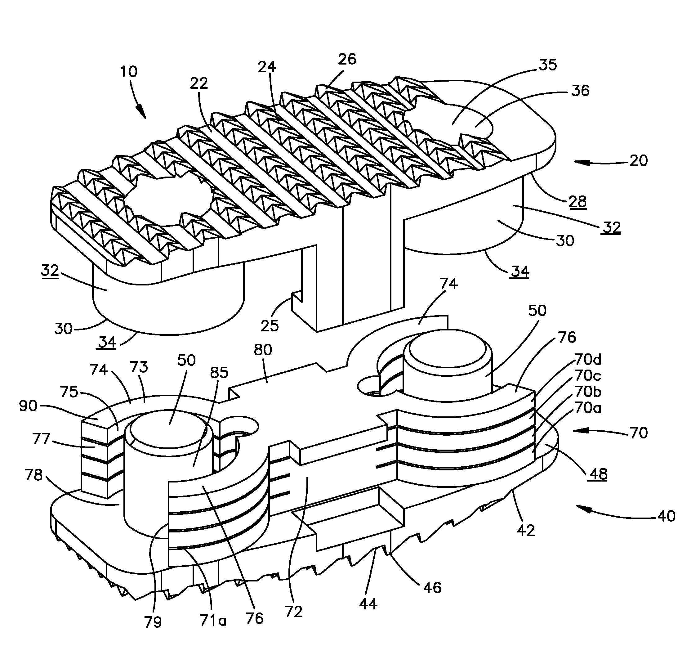
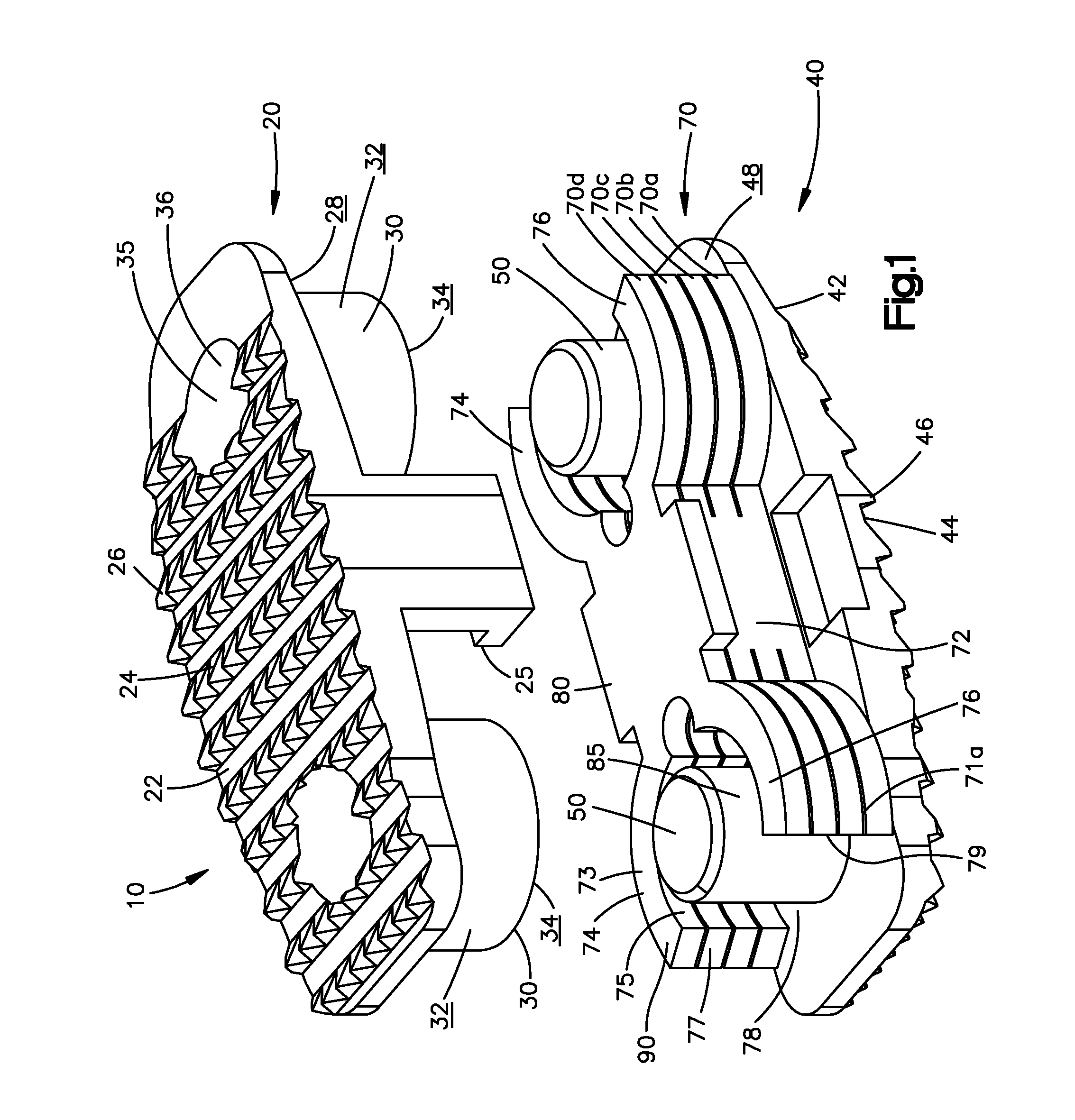
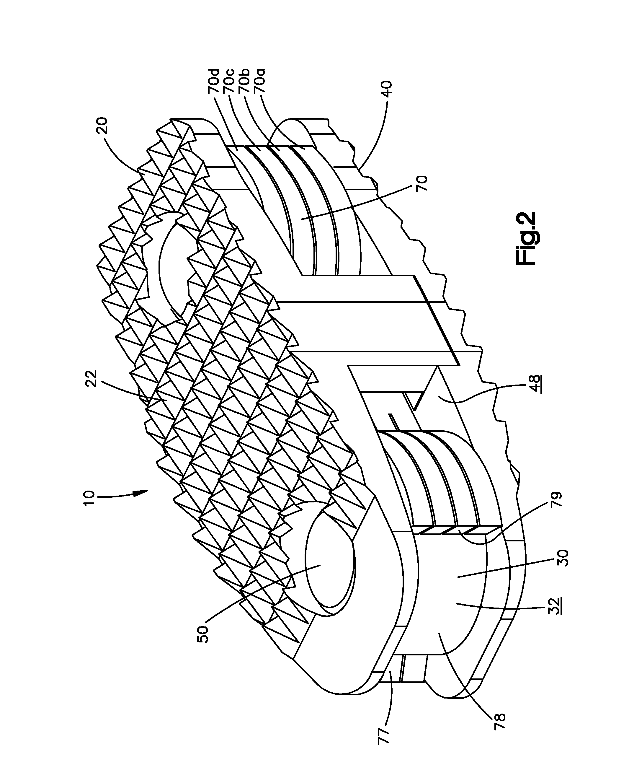
[0041]The superior component 20 of the first embodiment include two boss members 30, but is not so limited and may include a single or more than two boss members 30, protruding from an inferior surface 28 toward the inferior component 40 in an assembled configuration. The boss members 30 include a side surface 32 and a distal end surface 34. The inferior component 40 preferably includes two post members 50, but is also not so limited and may include a single or more than two post members 50, extending from a superior surface 48 toward the superior component 20 in the assembled configuration. Each of the post members 50 are operatively associated with the bosses 30 so that the boss members 30 are axially translatable relative to the post members 50 in the assembled configuration. The bosses 30 and the post members 50 are not limited to being arranged in the described and illustrated manner and may be arranged in an opposite manner or may be otherwise constructed to permit generally l...

second embodiment

[0056]The endplates 122, 142 of the interbody spacer 110 also include a pin / slot mechanism 185 on each side of the expandable interbody spacer 110 that preferably prevents overexpansion. More specifically, the inferior component includes tabs 190, one on each side, that extend up from the inferior component toward the superior component. The tabs 190 include a slot 192. The boss member 120 includes a central section which preferably has two bores 194. When the inferior component and superior component are assembled, bore 194 aligns with slot 192 and a pin 195 is inserted through the bore 194 and slot 192. The pin 195 is permitted to slide in the slot 192 as the superior and inferior components move relative to each other until the pin 195 contacts the ends of the slot 192 and acts as a stop mechanism 185 to prevent the spacer from disassembling. The spacer may have one or more tabs with slots, and corresponding bores and pins.

[0057]The footprint of the inferior and / or superior compo...


PUM


Abstract

An expandable interbody spacer (10) is provided that includes a pair of oppositely facing endplate components (20, 40) and an interior component that includes one or more vertically extending stacks of arranged C-clip members (70) radially surrounding one or more bosses (30) protruding interiorly from one of the endplates, wherein the size and configuration of the bosses and the c-clip members are designed to allow the incremental expansion of expandable interbody spacer.

Description

CROSS-REFERENCE TO RELATED APPLICATIONS[0001]This application claims the benefit of U.S. Provisional Application No. 61 / 034,713, filed on Mar. 7, 2008, entitled “EXPANDABLE INTERBODY SPACER DEVICE,” the contents of which is incorporated in its entirety by reference herein.BACKGROUND OF THE INVENTION[0002]Interbody fusion spacers are utilized to restore physiological space between two adjacent vertebrae and to maintain the space while fusion occurs between the adjacent vertebrae. The surgeries used to place such spacers can be painful for the patient and the size of the incision and approach channel provides challenges. It is desirable to develop an interbody spacer that promotes fusion while minimizing the size of the incision required for implantation of the spacer. An interbody spacer that assumes a collapsed configuration and subsequently deploys into an expanded configuration within the disc space may enable fusion while reducing the size of the required surgical incision. The s...

Claims


Application Information

Patent Timeline
Patent Type & Authority Patents(United States)
IPC IPC(8): A61F2/44
CPCA61F2/44A61F2/442A61F2/4455A61F2/446A61F2/4465A61F2/447A61F2002/30331A61F2002/30372A61F2002/30476A61F2002/30481A61F2002/30505A61F2002/30507A61F2002/3052A61F2002/30523A61F2002/3055A61F2002/30556A61F2002/30579A61F2002/30601A61F2002/30772A61F2002/30841A61F2002/448A61F2220/0025A61F2220/0033A61F2250/0009
Inventor MCMANUS, JOSHUAWOODBURN, WILLIAMWIDMER, WALTER
Owner DEPUY SYNTHES PROD INC
Why Eureka
Try Eureka