Automatic fishing device
A fishing device, automatic technology, applied in fishing accessories, fishing, application, etc., can solve the problems of insufficient compact arrangement, long overall length, heavy structure, etc., and achieve the effect of small structure, simple structure and easy portability
- Summary
- Abstract
- Description
- Claims
- Application Information
AI Technical Summary
Problems solved by technology
Method used
Image
Examples
Embodiment 1
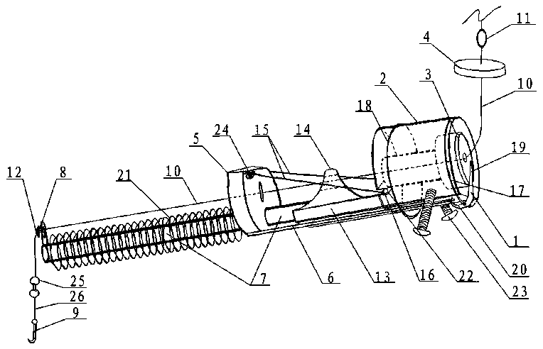
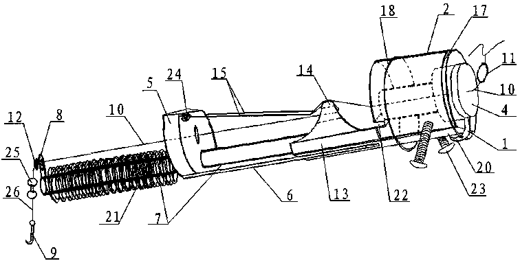
[0029] see figure 1 , figure 2 Shown: the present invention is an automatic fishing device, comprising a trigger lever 1, a base 2, a fixed magnet 3, a movable magnet 4, a slider 5, a connecting rod 6, a guide rod 7, a fishhook 9, a fishing line 10, a buoyancy The ball 11 and the stopper 12, the shaft of the trigger lever 1 is hinged on the base 2, and the base 2 is inlaid with a fixed magnet 3. In this embodiment, the shaft of the trigger lever 1 passes through the upper spring Ring 17 is hinged on base 2 . The upper spring ring 17 is fixed on the upper position of the base 2, and the trigger end 19 of the trigger lever 1 is placed on the outer surface of the fixed magnet 3 (the inner surface of the fixed magnet 3 is embedded in the base 2 and fits with the base 2, and the lower In the same), the trigger end 19 of the trigger lever 1 and the top surface of the fixed magnet 3 have a trigger height to complete the trigger action through the attraction of the movable magnet 4...
Embodiment 2
[0041] An automatic fishing device comprises a trigger lever, a base, a fixed magnet, a movable magnet, a sliding part, a connecting rod, a guide rod, a fishhook, a fishing line, a buoyancy ball and a stopper, and the shaft of the trigger lever is hinged on On the base, the base is inlaid with a fixed magnet. In this embodiment, the shaft of the trigger lever is hinged on the base through an upper spring ring. The trigger end of the trigger lever is placed in the outer surface of the fixed magnet, and there is a trigger height at which the trigger action is completed through the attraction of the movable magnet and the fixed magnet between the trigger end of the trigger lever and the top surface of the fixed magnet, and the connection end of the trigger lever Capable of snap-fitting with a connecting rod fixed on the slide.
[0042] The above-mentioned automatic fishing device also includes a guiding tongue and a wire puller, and the guide bar is spaced from left to right in t...
Embodiment 3
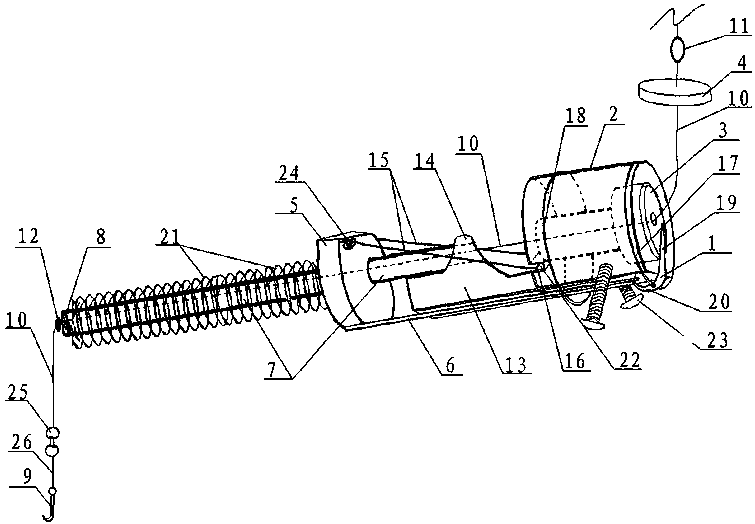
[0050] see image 3 , Figure 4 Shown: a kind of automatic fisher, comprises trigger lever 1, base 2, fixed magnet 3, movable magnet 4, sliding part 5, connecting rod 6, guide rod 7, fishhook 9, fishing line 10, buoyancy ball 11 and Limiting member 12, the shaft of the trigger lever 1 is hinged on the base 2, and the base 2 is inlaid with a fixed magnet 3. In this embodiment, the shaft of the trigger lever 1 is hinged through the upper spring ring 17 on base 2. The trigger end 19 of the trigger lever 1 is placed in the outer surface of the fixed magnet 3, and the trigger end 19 of the trigger lever 1 and the top surface of the fixed magnet 3 have a trigger to complete the trigger action by attracting the movable magnet 4 and the fixed magnet 3. height, the connecting end 20 of the trigger lever 1 can be fastened with the connecting rod 6 fixed on the slider 5 .
[0051] The above-mentioned automatic fishing device also includes a guide tongue 13 and a wire puller 15. The ba...
PUM
 Abstract
Description
Claims
Application Information
 - R&D
- Intellectual Property
- Life Sciences
- Materials
- Tech Scout
- Unparalleled Data Quality
- Higher Quality Content
- 60% Fewer Hallucinations
Browse by: Latest US Patents, China's latest patents, Technical Efficacy Thesaurus, Application Domain, Technology Topic, Popular Technical Reports.
© 2025 PatSnap. All rights reserved.Legal|Privacy policy|Modern Slavery Act Transparency Statement|Sitemap|About US| Contact US: help@patsnap.com


