Supercharge Your Innovation With Domain-Expert AI Agents!

Dual laser-power-level control and calibration system for burst-mode and continuous-mode transmitter

a laser power level control and calibration system technology, applied in semiconductor lasers, transmission monitoring, electromagnetic transmission, etc., can solve the problems of inability to converge during burst-on time, inability to achieve high frequency capability of transmitting diodes, and inability to control loop operation in burst-mode operation

Active Publication Date: 2013-11-05
MAXIM INTEGRATED PROD INC
View PDF21 Cites 2 Cited by
  • Summary
  • Abstract
  • Description
  • Claims
  • Application Information

AI Technical Summary

Problems solved by technology

Burst-mode operation adds complexity to the control loop operation due to the lack of data while BEN is low for the particular transmitter.
Since the minimum burst-on time is on the order of hundreds of nanoseconds and the typical loop time constant is at least an order of magnitude greater, converging during the burst-on time is normally not feasible.
However such monitor diodes and their associated circuitry do not have the high frequency capabilities of the transmitting diode, and accordingly, have real limitations with respect to what the monitor diode can accomplish.
While this can be done, it has the disadvantage of requiring the same to be done, typically periodically, so that changes in temperature do not let either value get out of control.
This of course provides an undesired interruption of data transmission.
This is costly to implement and may result in too few updates to reliably track the laser behavior.
Systems which require periodic occurrence of CIDs are not practical.
The problem, however, is that the optical power versus transmitting diode current is not linear, so that applying a fixed slope is, at best, a relatively rough approximation of the actual laser behavior.
However the same magnitude of error in the value of P0 cannot be tolerated because P0 is typically such a small value anyway.
The same error in P0 can cause a very large change in the extinction ratio, and may result in an Ibias value below the laser threshold, causing laser relaxation oscillations and unacceptable transmitting laser diode performance.

Method used


Image

  • Dual laser-power-level control and calibration system for burst-mode and continuous-mode transmitter
  • Dual laser-power-level control and calibration system for burst-mode and continuous-mode transmitter
  • Dual laser-power-level control and calibration system for burst-mode and continuous-mode transmitter

Examples


Embodiment Construction

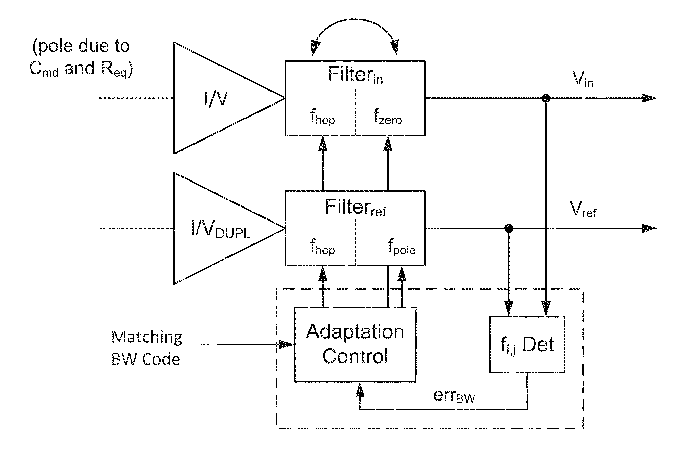
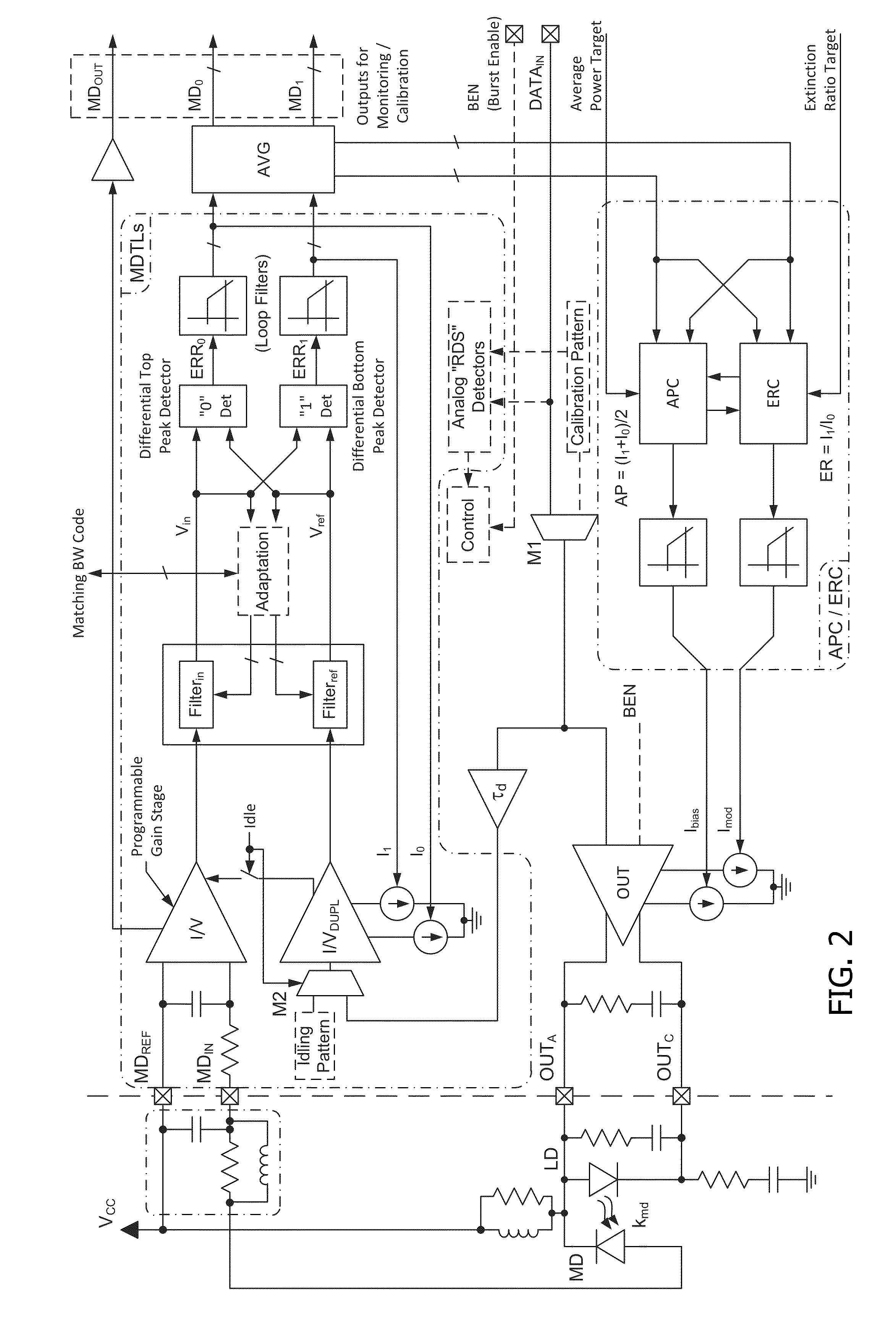
[0023]Now referring to FIG. 2, a block diagram of one embodiment of the present invention may be seen. Assume for the moment that the Burst Enable BEN is on. Accordingly the input data DATAIN is applied through the multiplexer M1 and the AND gate to a transconductance amplifier OUT and to a time delay circuit τd. The output of the transconductance amplifier OUT is connected to external circuitry including laser diode LD, the transmitter laser diode for the system. Part of the light emitted by the laser diode LD is coupled to monitor diode MD, which provides a monitor diode output current proportional to the light coupled thereto. This provides an input to the programmable gain stage transimpedance amplifier I / V as one input to the block labeled MDTLs (monitor diode tracking loops). At the same time, the output of the time delay τd is applied to transimpedance amplifier I / VDUPL through multiplexer M2. The transimpedance amplifier I / VDUPL amplifies the time delayed DATAIN signal to pr...


PUM


Abstract

Dual laser-power-level control and calibration system for burst-mode and continuous-mode transmitter. A first signal path receives a transmit signal that also drives the transmit laser, and a second signal path receives the output of a monitor diode. The first and second signal paths include filtering so that the two signal paths have a similar frequency response. The upper and lower excursions in both signal paths are compared, and the power levels of the optical transmitter are adjusted based on those comparisons. Embodiments with one control loop and two control loops are disclosed.

Description

CROSS-REFERENCE TO RELATED APPLICATIONS[0001]This application claims the benefit of U.S. Provisional Patent Application No. 61 / 408,532 filed Oct. 29, 2010 and U.S. Provisional Patent Application No. 61 / 409,418 filed Nov. 2, 2010.BACKGROUND OF THE INVENTION[0002]1. Field of the Invention[0003]The present invention relates to the field of solid state laser drivers.[0004]2. Prior Art[0005]Laser drivers of various designs are well known in the prior art. Such devices are used to drive solid state lasers in optical transmitters for optical transmission of data over fiber optic lines. These devices are capable of high data rates, and accordingly, are finding ever increasing application in data communications. Solid state lasers, however, have various characteristics that must be accounted for in such applications. One such characteristic is that, at least for high data rates, solid state lasers are not operated between on and off conditions because of the time it takes for the laser, when...

Claims


Application Information

Patent Timeline
Patent Type & Authority Patents(United States)
IPC IPC(8): H01S3/00
CPCH01S5/0683H01S5/06832
Inventor NGUYEN, JAMES CONGLA VOIE, MATTHEW CHRISTOPHERFILIP, JAN
Owner MAXIM INTEGRATED PROD INC
Features
  • R&D
  • Intellectual Property
  • Life Sciences
  • Materials
  • Tech Scout
  • Unparalleled Data Quality
  • Higher Quality Content
  • 60% Fewer Hallucinations
Learn More