Pre-equalized optical transmitter and pre-equalized optical transmission system

a technology of optical transmission system and pre-equalization, applied in the field of optical information transmission technology, can solve the problems of limited pre-equalization performance and difficulty in transmission, and achieve the effect of increasing the pre-equalization transmission performance and practicality

Inactive Publication Date: 2009-09-24
HITACHI LTD
View PDF4 Cites 98 Cited by
  • Summary
  • Abstract
  • Description
  • Claims
  • Application Information

AI Technical Summary

Benefits of technology

[0035]According to an embodiment of this invention, it is possible, by preventing the information signal from leaking outside the Nyquist bandwidth, to increase the pre-equalization transmission performance and the practicality of the 1 sample / bit optical duo-binary signal.

Problems solved by technology

Moreover, when the chromatic dispersion tolerance is small, an error is generated in measurement of chromatic dispersion of a transmission line, and the chromatic dispersion is not correctly obtained, resulting in difficulty of transmission.
For the conventional 1 sample / bit optical duo-binary pre-equalization transmitter, the performance of the pre-equalization is limited.

Method used


Image

  • Pre-equalized optical transmitter and pre-equalized optical transmission system
  • Pre-equalized optical transmitter and pre-equalized optical transmission system
  • Pre-equalized optical transmitter and pre-equalized optical transmission system

Examples


first embodiment

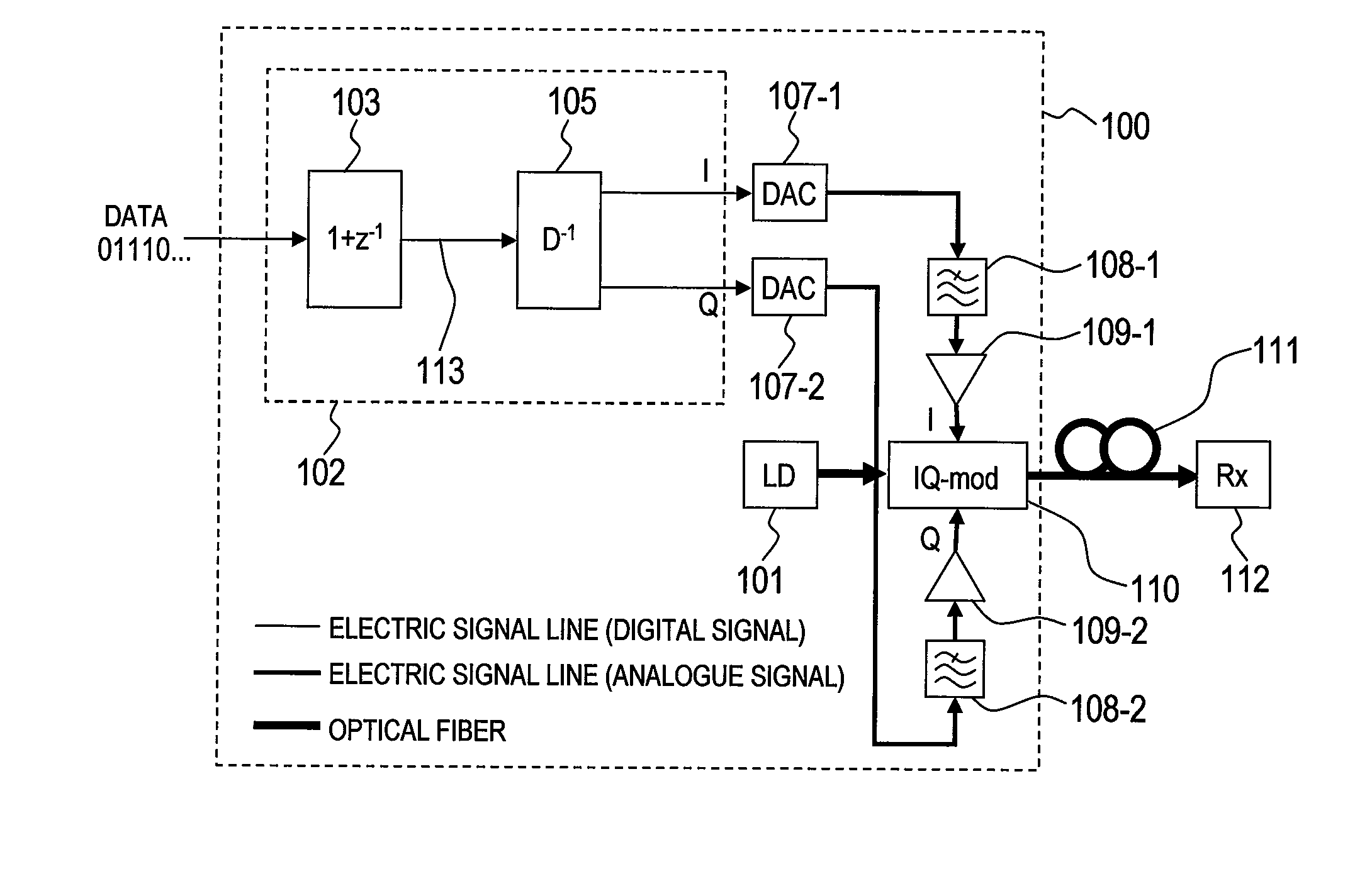
[0062]FIG. 3 is a block diagram of a configuration of an optical transmission system according to a first embodiment of this invention.

[0063]Routes of digital signals are represented by thin lines, routes of high-speed analogue electric signals are represented by medium lines, and routes of optical signals are represented by thick lines. In an example described below, a binary information signal is converted into a ternary duo-binary signal to be transmitted. For the binary information signal, the bit rate and the symbol rate (baud rate) coincide with each other, and hence both of them have the same meaning in this case. However, as described later, this embodiment can be applied to a multi-valued information signal, and, in this case, transmission as 1 sample / symbol is necessary.

[0064]In the optical transmission system illustrated in FIG. 3, a 1 sample / bit pre-equalization optical duo-binary transmitter 100 inputs a non-modulated laser light output from a laser source 101 to an opt...

second embodiment

[0092]FIG. 6 is a configuration diagram of an optical transmission system according to a second embodiment of this invention, and a post-filter response equalizing filter 106 is added to the 1 sample / bit optical duo-binary pre-equalization transmitter 100 according to the first embodiment of this invention.

[0093]The post-filter response equalizing filter 106 is realized by a 1 sample / bit digital filter, and is a circuit for equalizing in advance an impulse response (time response) of the post filters 108-1 and 108-2.

[0094]FIGS. 7A and 7B illustrate optical waveforms showing an effect of the post-filter response equalizing filter 106, and an example illustrated in FIG. 7A is optical waveforms after pre-equalization transmission (pre-equalization rate: 100%) when the post-filter response equalizing filter 106 is not used. In the example illustrated in FIG. 7A, an 11-th order Butterworth filter −3 dB bandwidth of 0.4 Rb is used as the post filters 108-1 and 108-2. The post filters 108-...

third embodiment

[0112]In a third embodiment of this invention, by employing the optical interference effect in the digital signal processing, the chromatic dispersion tolerance of the generated 1 sample / bit optical duo-binary signal can increase to approximately four times that of the NRZ signal. As a result, even when a measurement of the chromatic dispersion of a transmission line includes an error, or when the chromatic dispersion changes, the pre-equalization transmission can be provided, thereby eliminating superfluous configurations such as a variable CD compensation circuit.


PUM


Abstract

Provided is a pre-equalized optical transmitter, comprises: a laser source; a duo-binary pre-coder circuit; a pre-equalization circuit for applying an inverse function of chromatic dispersion; at least two D/A converters; and an optical field modulator comprising at least two input terminals for an electric signal. The pre-equalized optical transmitter: converts, by the duo-binary pre-coder circuit, a digital information signal of a predetermined symbol time to be transmitted into a digital complex signal including one sampling point per symbol; equalizes, by the pre-equalization circuit, degradation in transmission of the digital complex signal; converts, by the D/A converters, the equalized digital complex signal into an analogue signal; suppresses an analogue signal leaking outside a Nyquist bandwidth by at least 23 dB; modulates, by the optical field modulator, light output from the laser source with the analogue signal to generate a modulated optical field signal; and transmits the modulated optical field signal.

Description

CLAIM OF PRIORITY[0001]The present application claims priority from Japanese patent application 2008-71260 filed on Mar. 19, 2008, the content of which is hereby incorporated by reference into this application.BACKGROUND OF THE INVENTION[0002]This invention relates to a technology of optical information transmission, and more particularly, to a technology suitable for transmission and reception of an optical signal transmitted via an optical fiber.[0003]For transmission through an extremely high-speed optical fiber, a modulation speed and a transmission distance are limited by chromatic dispersion (CD), polarization mode dispersion (PMD), and bandwidth limit of the optical fiber and components used for the optical fiber.[0004]The chromatic dispersion (CD) is a phenomenon in which light waves different in wavelength are transmitted at different speeds in an optical fiber. An optical spectrum of an optical signal modulated at high speed includes different wavelength components, and th...

Claims


Application Information

Patent Timeline
Patent Type & Authority Applications(United States)
IPC IPC(8): H04B10/04H04B10/2507H04B10/2513H04B10/2525H04B10/516H04B10/61
CPCH04B10/25137H04B2210/254H04B10/5055
Inventor KIKUCHI, NOBUHIKO
Owner HITACHI LTD
Why Eureka
Try Eureka