Method for fabricating condenser microphone and condenser microphone

a technology of condenser microphone and condenser microphone, which is applied in the direction of solid-state devices, basic electric elements, transistors, etc., can solve the problems of poor adhesion between the composite diaphragm chip b>101/b> and the fixed electrode chip b>102/b>, difficult to obtain a high-power signal with excellent reliability, and reduce the parasitic capacitance of the condenser microphone. , to achiev

Active Publication Date: 2007-11-29
PANASONIC CORP
View PDF6 Cites 28 Cited by
  • Summary
  • Abstract
  • Description
  • Claims
  • Application Information

AI Technical Summary

Benefits of technology

[0028]According to the condenser microphone of the present invention and the fabrication method for the same, the first semiconductor chip formed with the fixed electrode is metallically bonded to the second semiconductor chip formed with the vibrat

Problems solved by technology

However, since the two chips are packaged with the insulating spacers 110 interposed therebetween, the adhesion between the composite diaphragm chip 101 and the fixed electrode chip 102 is poor.
This reduces the tolerance of the ECM 100 to vi

Method used


Image

  • Method for fabricating condenser microphone and condenser microphone
  • Method for fabricating condenser microphone and condenser microphone
  • Method for fabricating condenser microphone and condenser microphone

Examples


Embodiment Construction

[0033]An embodiment of the present invention will be described hereinafter with reference to the drawings. For simplicity, components having substantially the same function are represented by the same reference numerals. The present invention is not limited to the embodiment described below.

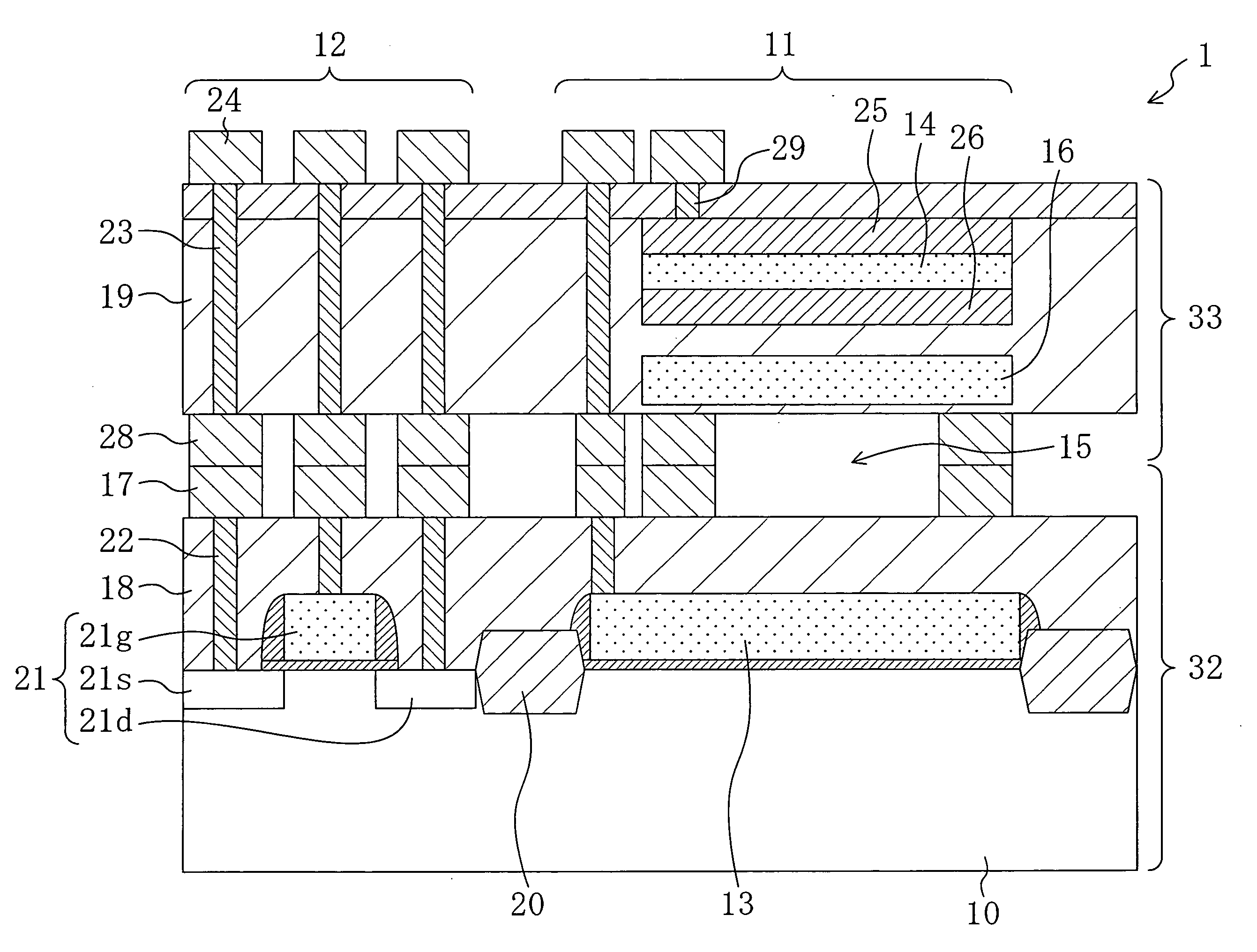
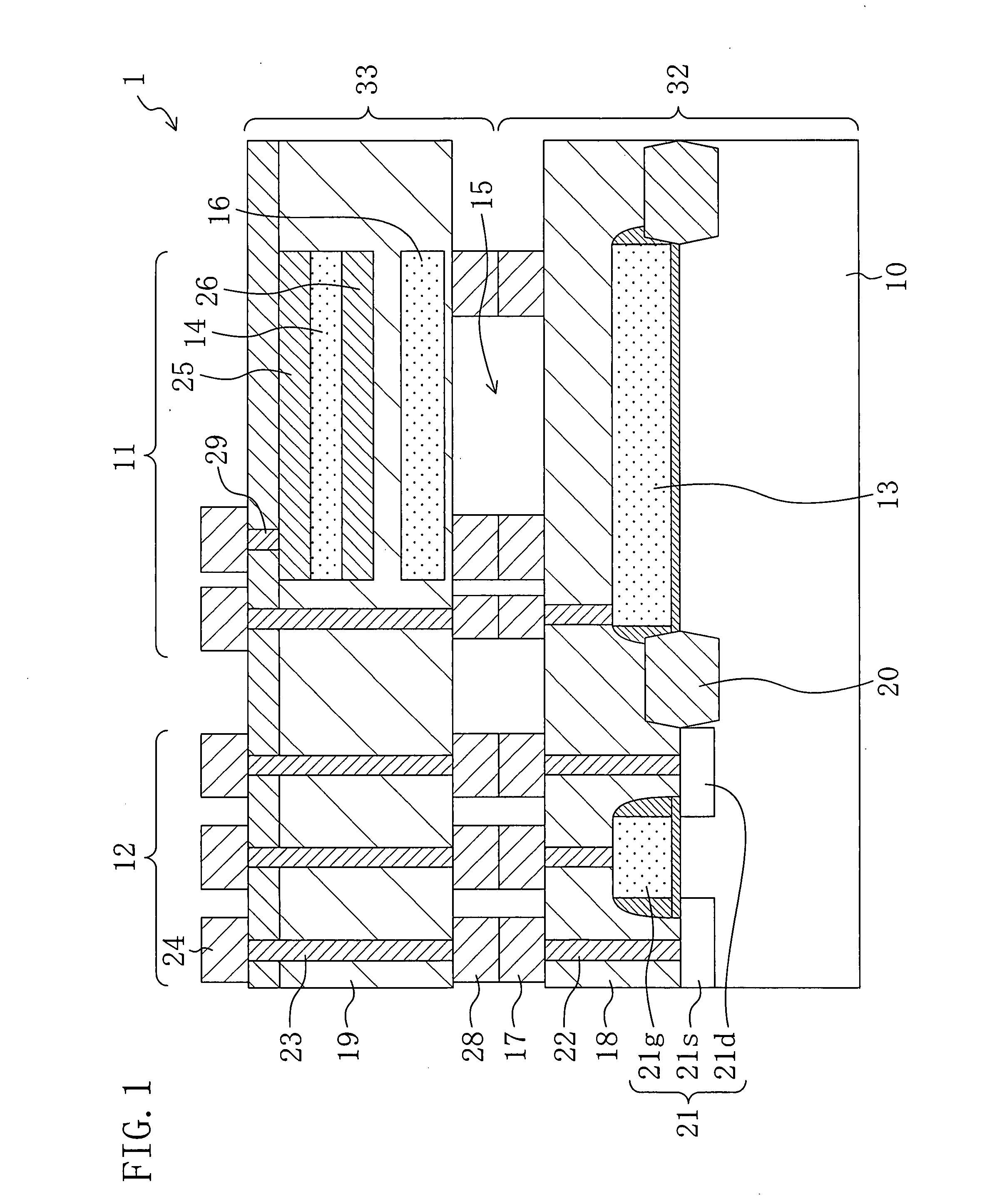
[0034]FIG. 1 is a cross-sectional view schematically illustrating the structure of an electret condenser microphone (acoustic sensor) 1 according to this embodiment. The condenser microphone 1 of this embodiment includes a condenser region 11 and a detection circuit region 12 which are connected through a wire (unshown) to each other.

[0035]As illustrated in FIG. 1, the condenser microphone 1 includes a lower electrode (fixed electrode) 13, an upper electrode (vibrating electrode) 14 and an air gap 15 and is configured such that a first semiconductor chip 32 formed with the lower electrode 13 and a second semiconductor chip 33 formed with the upper electrode 14 are opposed to each other with the a...


PUM


Abstract

A first semiconductor chip includes a fixed electrode formed on a first semiconductor substrate and a plurality of first metal spacers formed on a first interlayer dielectric. A second semiconductor chip includes a vibrating electrode formed on a second semiconductor substrate and a plurality of second metal spacers formed on a second interlayer dielectric. The first and second semiconductor chips are metallically bonded to each other using the first and second metal spacers. An air gap is formed in a region of the condenser microphone located between the first semiconductor chip and the second semiconductor chip except bonded regions of the first and second metal spacers.

Description

CROSS-REFERENCE TO RELATED APPLICATIONS[0001]The disclosure of Japanese Patent Application No. 2006-092354 filed on Mar. 29, 2006 including specification, drawings and claims is incorporated herein by reference in its entirety.BACKGROUND OF THE INVENTION[0002](1) Field of the Invention[0003]The present invention relates to methods for fabricating high-reliability condenser microphones, which allow the condenser microphones to be reduced in size, and condenser microphones.[0004](2) Description of Related Art[0005]Known condenser microphones (acoustic sensors) have been each constructed such that a sound wave detector and a detection circuit are formed on individual substrates and the substrates are packaged with insulating spacer layers interposed therebetween (see, for example, Japanese Unexamined Patent Publication No. 2003-163996).[0006]FIG. 6 is a cross-sectional view illustrating the structure of an electret condenser microphone (ECM) described in Japanese Unexamined Patent Publ...

Claims


Application Information

Patent Timeline
IPC IPC(8): H01L29/84H01L21/768
CPCH01L25/162H01L27/0629H01L28/60H01L29/78H01L2924/0002H04R19/04H01L2924/00
Inventor MORI, MITSUYOSHITANAKA, KEISUKEYAMAGUCHI, TAKUMIKATAYAMA, TAKUMA
Owner PANASONIC CORP
Why Eureka
Try Eureka