Implantable Medical Device

Active Publication Date: 2008-10-23
ST JUDE MEDICAL
View PDF2 Cites 24 Cited by
  • Summary
  • Abstract
  • Description
  • Claims
  • Application Information

AI Technical Summary

Benefits of technology

[0028]Regardless of the number of cooperating metal elements and metal members, the header can be welded to housing in a single or in several locations. An advantage of using several welding locations is that a strong joint is achieved, since forces exerting a torque on the joint are better distributed. Furthermore, the header will be subjected to less heat.
[0029]According to one embod

Problems solved by technology

A disadvantage with this known method is that it is complex and time consuming.
A disadvantage with this known device is that only very small tolerances are acceptable and that, in view of the size of the components, the mounting operation will be complicated and difficult.
A problem with this known device

Method used


Image

  • Implantable Medical Device
  • Implantable Medical Device
  • Implantable Medical Device

Examples


first embodiment

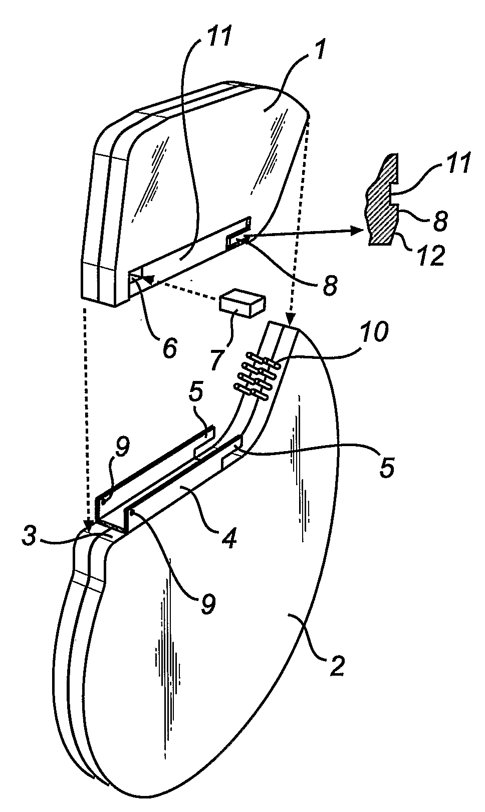
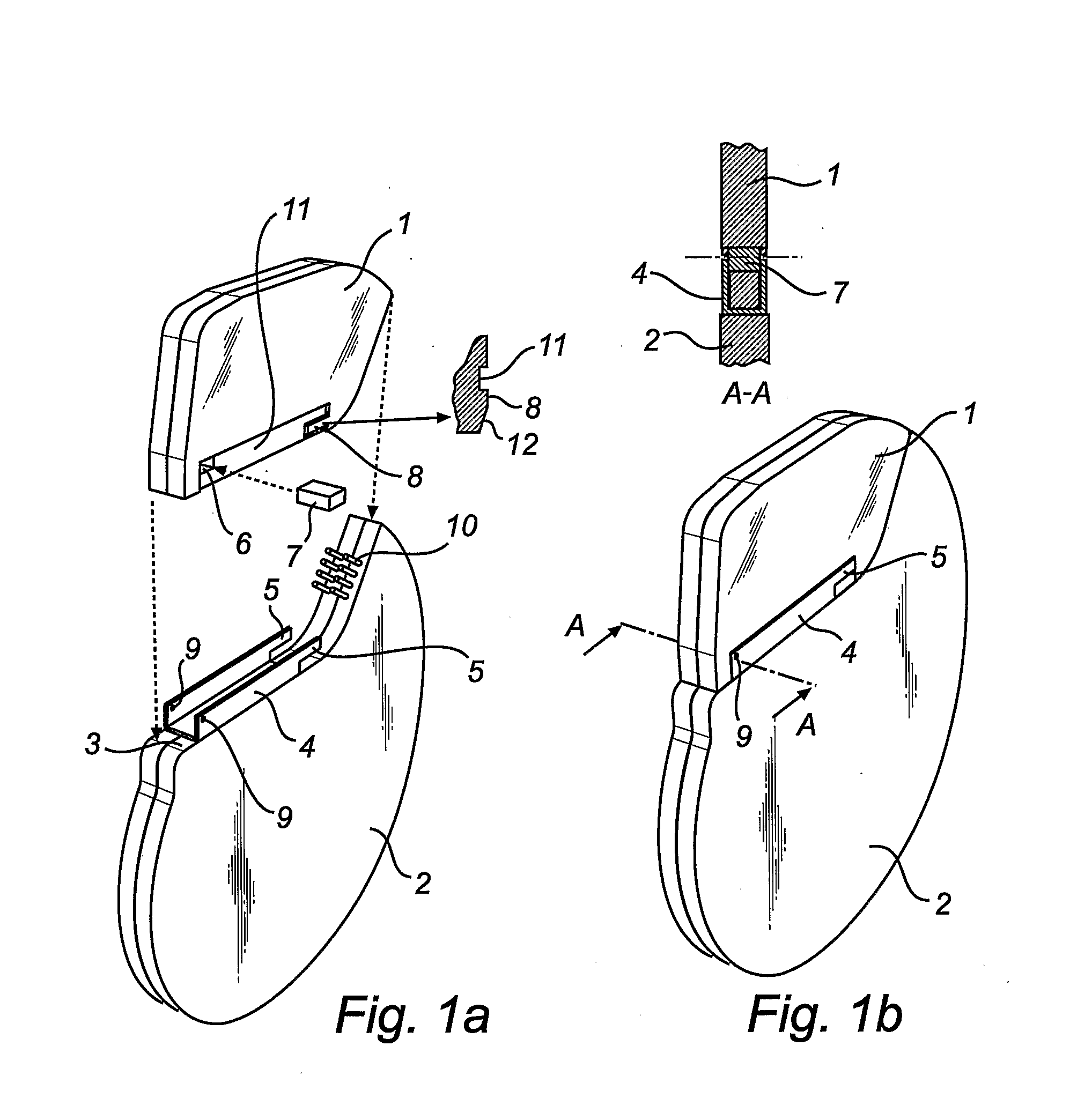
[0038]With reference to FIGS. 1a, 1b and 2a, an implantable medical device according to the invention is shown. The implantable medical device according to the example is a pacemaker. The pacemaker includes a pre-fabricated header in the form of a pre-molded header 1 made of polyurethane. The pacemaker further includes a hermetically sealed housing 2 formed of titanium. The housing 2 is provided with feedthrough terminals 10 that are electrically connected to the electronic circuits inside the hermetically sealed housing 2. The header 1 is provided with a connector receptacle for receiving a connector pin at the proximal end of a pacing lead (not shown).

[0039]A housing fastener part formed of metal and in the form of a U-shaped bracket 4 is attached to the housing 2 by welding. The bracket 4 is attached to a surface 3 of the housing 2 which faces the header 1 when the header 1 and the housing 2 are fastened together. The bracket 4, extends along a mayor portion of the surface 3. The...

second embodiment

[0054]In FIG. 4, an alternative embodiment of the housing fastener part is shown. Instead of the U-shaped bracket 4 in the previous embodiments, a housing fastener part formed of metal and in the form of two L-shaped brackets 4 is attached to the housing 2 by welding. In this embodiment, the header 1 is provided with two metal elements 7 that are arranged in corresponding recesses 6 in the header 1. The metal elements 7 do not extend through the thickness of the header 1, but protrude at one side thereof, respectively. In the mounted implantable medical device, the exposed end of each metal member 7 is welded to a corresponding L-shaped bracket 4. This will provide a joint essentially equivalent to the joint of the

[0055]In FIG. 5, another alternative embodiment of the housing fastener part is shown. The housing fastener part is formed of metal in the form of one L-shaped bracket 4 which is attached to the housing 2 by welding. In this embodiment, the header 1 is provided with two me...


PUM


Abstract

In an implantable medical device and a method for assembly thereof, a hermetically sealed housing encloses electronic circuitry and has a housing fastener part that is formed of metal and that protrudes from the housing. A per-fabricated header, for receiving conducting leads and for connecting the conducting leads to the electronic circuitry, has a header fastener part also formed of metal. The header is fastened to the housing by metal-to-metal welding of the housing fastener part and the header fastener part at a distance from the housing.

Description

BACKGROUND OF THE INVENTION[0001]1. Field of the Invention[0002]The present invention relates to an implantable medical device and to a method for assembling an implantable medical device. It further relates to a pre-fabricated header and to a hermetically sealed housing for use in an implantable medical device.[0003]The present invention is applicable to a variety of implantable medical devices of the type having a pre-fabricated part to be coupled to a housing part. Examples of such devices are heart stimulators such as cardiac pacemakers and implantable cardioverter-defibrillators (ICD's). However, the invention and its background will be described herein in terms of a specific example of such implantable devices, namely cardiac pacemakers.[0004]2. Description of the Prior Art[0005]Present day cardiac pacemakers are typically designed to be implanted in a “pocket” of fatty tissue near the patient's upper chest or lower abdomen. Accordingly, electronic circuits within the pacemake...

Claims


Application Information

Patent Timeline
IPC IPC(8): A61N1/375H05K5/06
CPCA61N1/3752
Inventor SJOSTEDT, JOHAN
Owner ST JUDE MEDICAL
Why Eureka
Try Eureka