Electromagnetic tags

a technology of electromagnetic tags and tags, applied in the field of tags, can solve the problems of easy corruption of information communicated to and from tags, easy to be stolen, and difficult to detect or hide,

Active Publication Date: 2007-06-14
XEROX CORP
View PDF5 Cites 104 Cited by
  • Summary
  • Abstract
  • Description
  • Claims
  • Application Information

AI Technical Summary

Problems solved by technology

Others are designed to be hard to detect or hidden.
Unfortunately, tags, readers, and / or writers can be compromised by malicious entities such that the information communicated to and from a tag can be corrupted and / or stolen.
In addition, it may not be possible for the holder of a tag or reader to detect misbehavior since the communication medium may be undetectable by individuals.
Moreover, many individuals do not have intuitions about the behavior of electrostatic, magnetic and / or electro-magnetic communication mediums that allow them to make safe assumptions about the security of their tags.

Method used


Image

  • Electromagnetic tags
  • Electromagnetic tags
  • Electromagnetic tags

Examples


Embodiment Construction

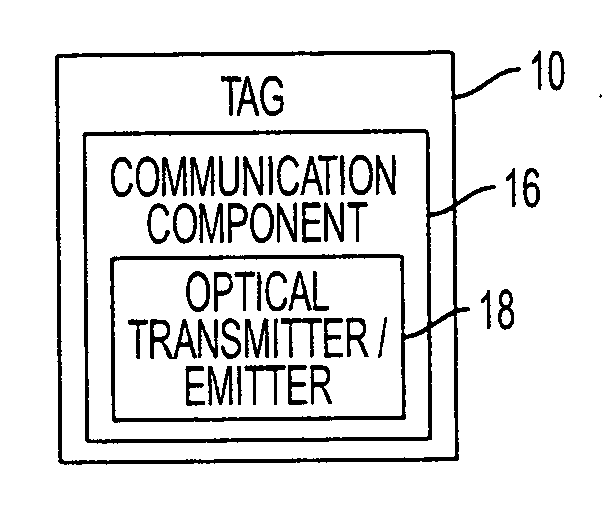
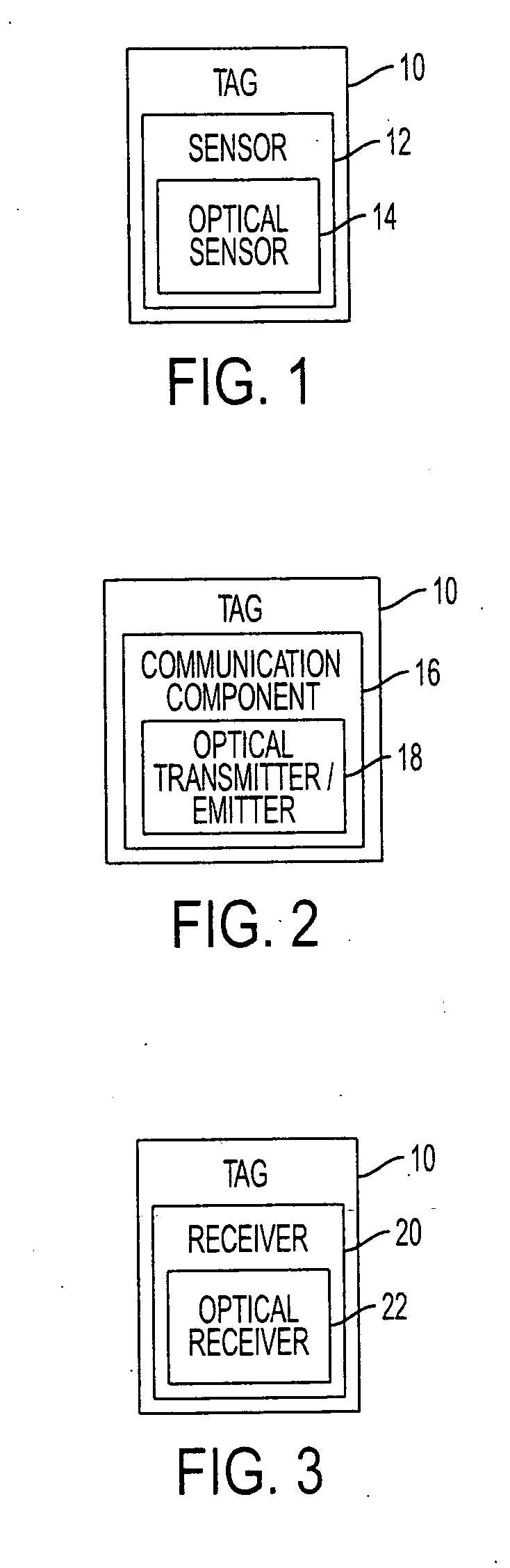
[0013]FIG. 1 illustrates a tag 10 that is invoked by electromagnetic (EM) radiation, as well as other invoking sources. Examples of suitable invocation include toggling a state (e.g., “on” and “off”, etc.) of the tag 10, persisting a state of the tag 10 (e.g., maintaining an “on” state), transitioning a state (e.g., from “idle” to “wake,”“lower power” to “higher power,” any state to “read,”“write,” or “erase” state, etc.) of the tag 10, etc. Suitable EM radiation encompasses the electromagnetic spectrum. For example, in one instance, the invoking EM radiation corresponds to the visible and / or non-visible light portion (e.g., from about 300 GHz to about 300 EHz) of the electromagnetic spectrum. This portion of the electromagnetic spectrum includes infrared (IR), visible, ultraviolet (UV), x-rays, and gamma rays. In another instance, the invoking EM radiation alternatively or additionally includes the radio frequency portion (e.g., from about 30 Hz to about 300 GHz) of the electromagn...


PUM


Abstract

An electromagnetic tag includes a communication component, which includes an optical transmitter / emitter that transmits / emits optically encoded information.

Description

BACKGROUND [0001] The following generally relates to tags. More particularly, it is directed to electromagnetic tags such as optical tags. However, essentially all passive and / or active tags are contemplated. [0002] Conventional tagging technology includes passive and active tags. Passive tags generally include the broad category of tags that are visually readable by a human, but do not have signal reception, transmission / emission, computation, and / or storage capabilities. Examples of such tags include price tags, washing directions on clothing, etc. Some passive tags are discernable, but not readable (e.g., bar codes, glyphs, etc.). Others are designed to be hard to detect or hidden. One example of such a tag is a watermark, which is a human-invisible manipulation of an image used to encode data. [0003] Active tags provide signal reception, transmission / emission, computation, and / or storage capabilities. Some are self-powered, either by battery or other source, while others are pow...

Claims


Application Information

Patent Timeline
Patent Type & Authority Applications(United States)
IPC IPC(8): G08B13/14G06K19/06H04B10/00
CPCG06K19/0723G06K19/0728G06K19/07345G06K19/145G08B13/1481H04B10/1143
Inventor STEWART, PAUL J.SMETTERS, DIANA K.FORK, DAVID K.
Owner XEROX CORP
Why Eureka
Try Eureka