Optical system comprising an FM source and a spectral reshaping element

a technology of optical system and spectral reshaping element, applied in the field of signal transmission, to achieve the effect of increasing the tolerance of fiber dispersion and extending the optical transmission length

Inactive Publication Date: 2006-02-09
II VI DELAWARE INC
View PDF19 Cites 97 Cited by
  • Summary
  • Abstract
  • Description
  • Claims
  • Application Information

AI Technical Summary

Benefits of technology

[0019] This invention provides an optical spectrum reshaper (OSR) which works in tandem with a modulated optical source which, by modifying the spectral properties of the modulated signal, results in extending the optical transmission length well beyond the dispersion limit. The OSR can be defined as a passive optical element that imparts an optical frequency dependent loss and frequency dependent phase on an input optical signal. This invention also provides a modulated laser source and an optical spectrum reshaper system that increases tolerance to fiber dispersion as well as converting a partially frequency modulated signal into a substantially amplitude modulated signal.

Problems solved by technology

On the other hand, directly modulated lasers (DML) reach <5 km because their inherent time dependent chirp causes severe distortion of the signal after this distance.

Method used


Image

  • Optical system comprising an FM source and a spectral reshaping element
  • Optical system comprising an FM source and a spectral reshaping element
  • Optical system comprising an FM source and a spectral reshaping element

Examples


Embodiment Construction

[0076] Many modifications, variations and combinations of the methods and systems and apparatus of a dispersion compensated optical filter are possible in light of the embodiments described herein. The description above and many other features and attendant advantages of the present invention will become apparent from a consideration of the following detailed description when considered in conjunction with the accompanying drawings wherein like numbers refer to like parts and further wherein:

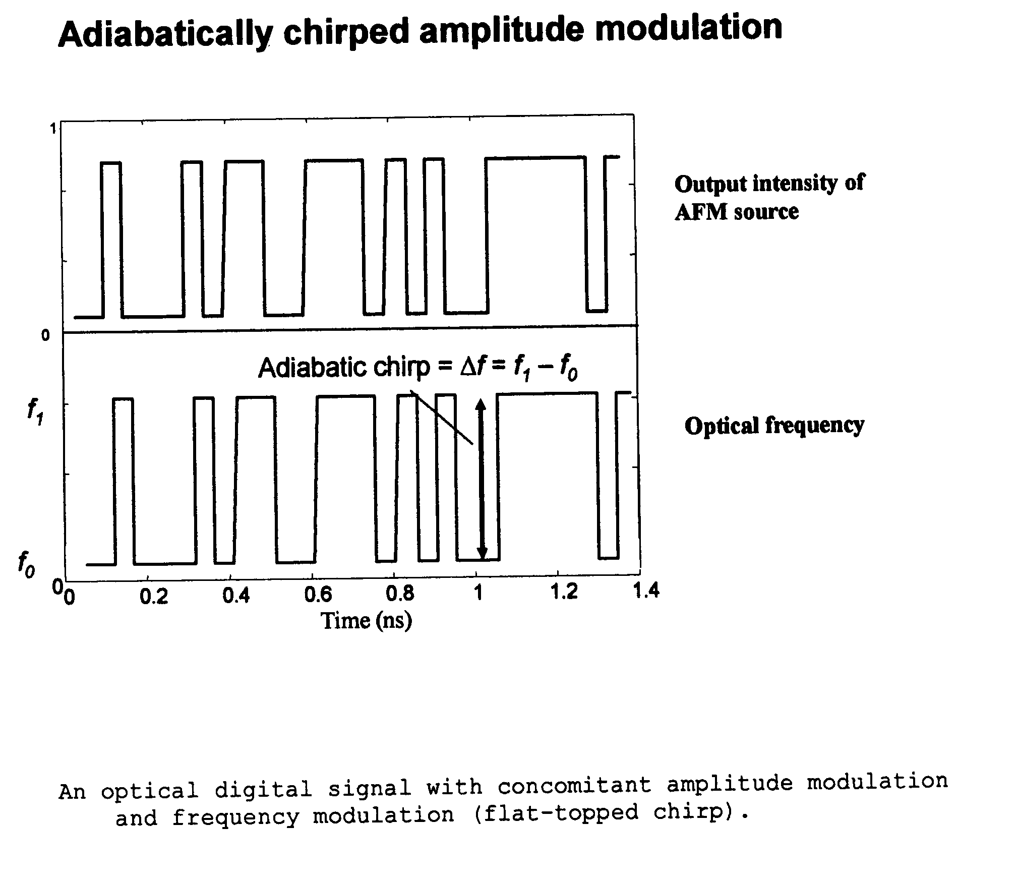
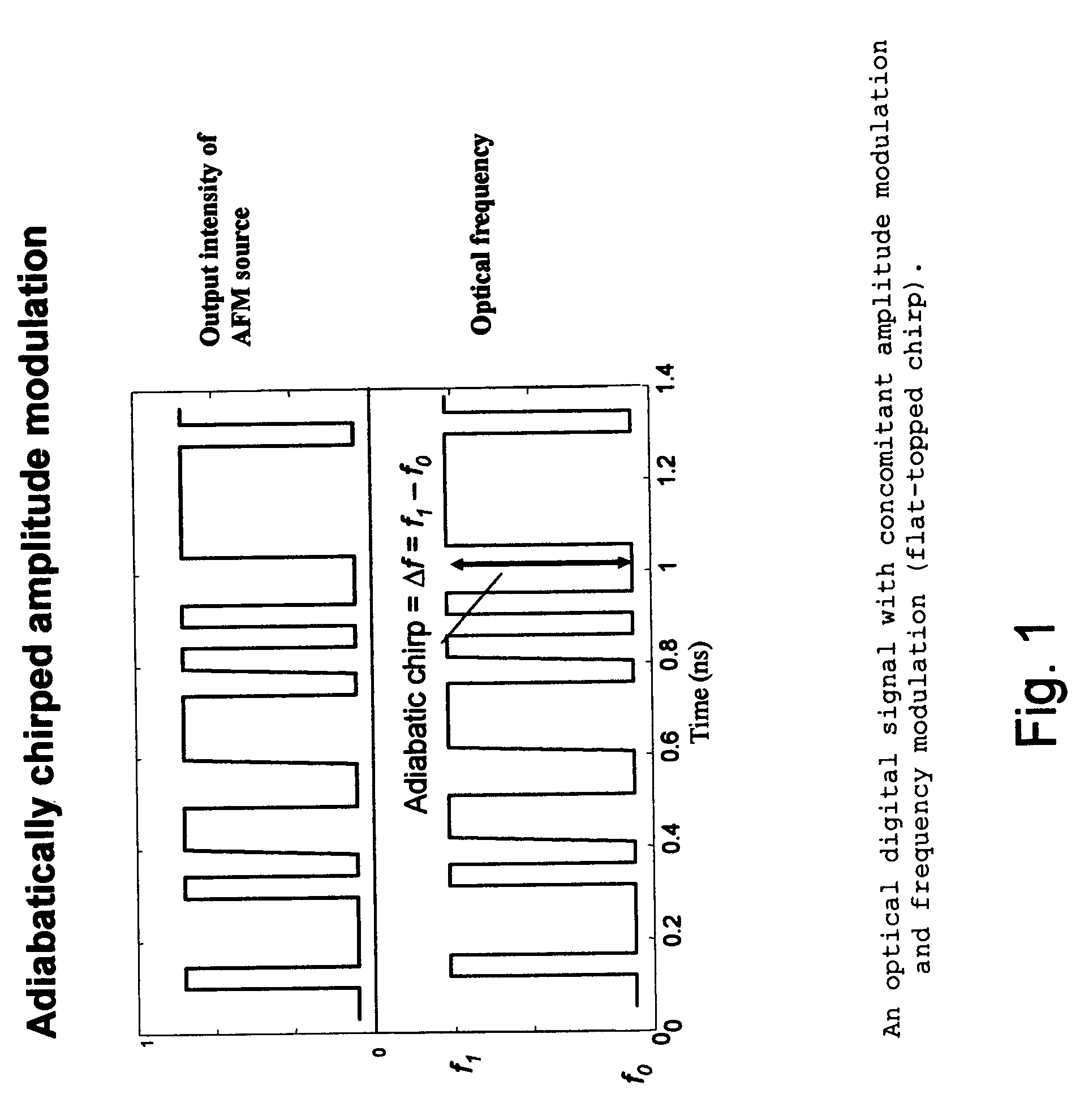
[0077]FIG. 1 illustrates an optical digital signal with concomitant amplitude modulation and frequency modulation (i.e., flat-topped chirp);

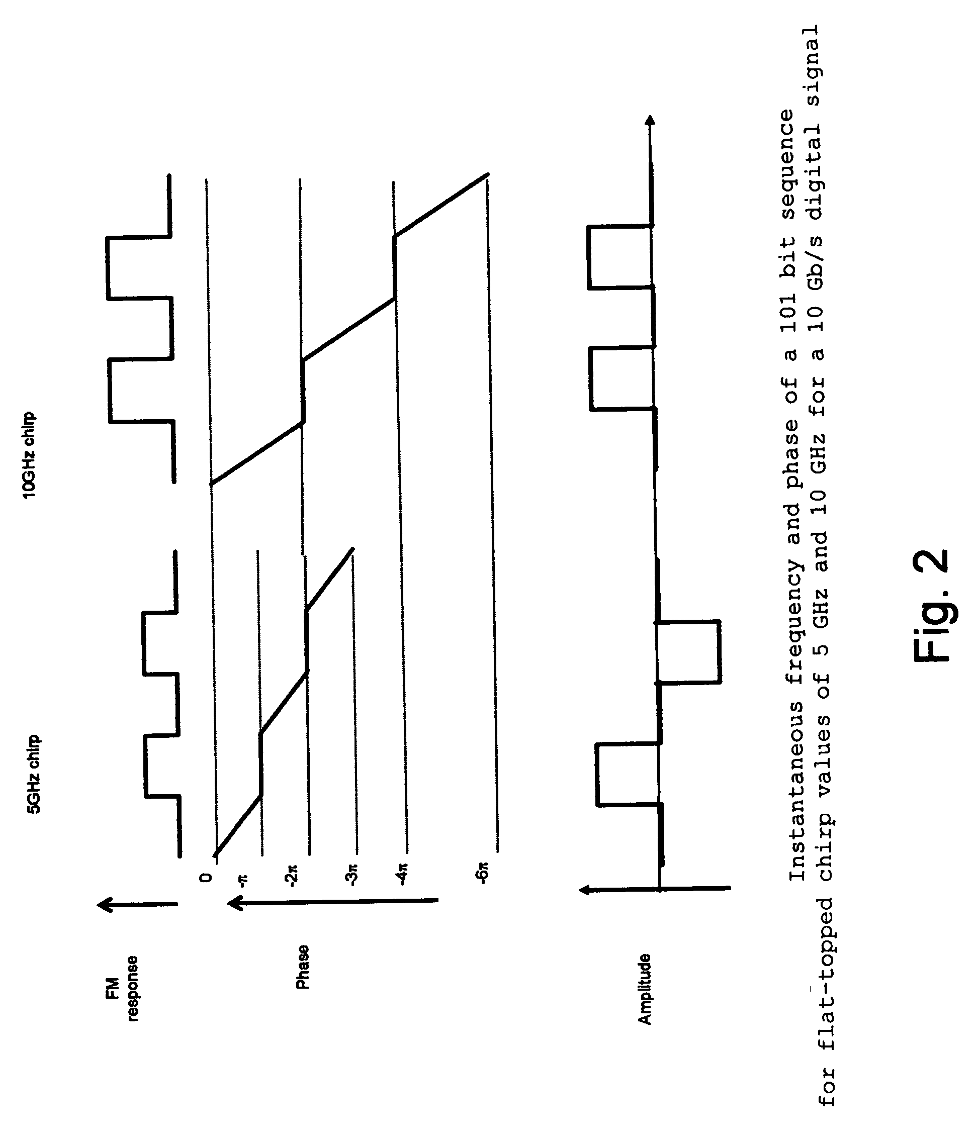
[0078]FIG. 2 illustrates the instantaneous frequency and phase of a 101 bit sequence for flat-topped chirp values of 5 GHz and 10 GHz for a 10 Gb / s digital signal;

[0079]FIG. 3 illustrates a 101 bit sequence with (CML output) and without (Standard NRZ) flat-topped chirp before and after propagation;

[0080]FIG. 4 illustrates a Gaussian pulse with adiabatic ...


PUM


Abstract

In one form of the present invention, there is provided a fiber optic communication system comprising: an optical signal source adapted to receive a base binary signal and produce a first signal, said first signal being frequency modulated; and an optical spectrum reshaper adapted to reshape the first signal into a second signal, said second signal being amplitude modulated and frequency modulated; characterized in that: the frequency characteristics of said first signal, and the optical characteristics of said optical spectrum reshaper, being such that the frequency characteristics of said second signal are configured so as to increase the tolerance of the second signal to dispersion in a transmission fiber. In another form of the present invention, there is provided an optical transmitter comprising: a frequency modulated source for generating a first frequency modulated signal, and an amplitude modulator for receiving the first frequency modulated signal and for generating a second amplitude and frequency modulated signal. In another form of the present invention, there is provided a method for transmitting an optical signal through a transmission fiber comprising: receiving a base binary signal; operating an optical signal source using the base binary signal to produce a first signal, said first signal being frequency modulated; passing the frequency modulated signal through an optical spectrum reshaper so as to reshape the first signal into a second signal, said second signal being amplitude modulated and frequency modulated; the frequency characteristics of said first signal, and the optical characteristics of said optical spectrum reshaper, being such that the frequency characteristics of said second signal are configured so as to increase the tolerance of the second signal to dispersion in a transmission fiber; and passing the second signal through a transmission fiber. In another form of the present invention, there is provided a method for transmitting a base signal, comprising: using the base signal to produce a frequency modulated signal; and providing an amplitude modulator for receiving the frequency modulated signal and for generating an amplitude and frequency modulated signal.

Description

REFERENCE TO PENDING PRIOR PATENT APPLICATIONS [0001] This patent application: [0002] (i) is a continuation-in-part of pending prior U.S. patent application Ser. No. 10 / 289,944, filed Nov. 6, 2002 by Daniel Mahgerefteh et al. for POWER SOURCE FOR A DISPERSION COMPENSATION FIBER OPTIC SYSTEM (Attorney's Docket No. TAYE-59474-00006); [0003] (ii) is a continuation-in-part of pending prior U.S. patent application Ser. No. 10 / 308,522, filed Dec. 3, 2002 by Daniel Mahgerefteh et al. for HIGH-SPEED TRANSMISSION SYSTEM COMPRISING A COUPLED MULTI-CAVITY OPTICAL DISCRIMINATOR (Attorney's Docket No. TAYE-59474-00007); [0004] (iii) is a continuation-in-part of pending prior U.S. patent application Ser. No. 10 / 680,607, filed Oct. 6, 2003 by Daniel Mahgerefteh et al. for FLAT DISPERSION FREQUENCY DISCRIMINATOR (FDFD) (Attorney's Docket No. TAYE-59474-00009); [0005] (iv) claims benefit of pending prior U.S. Provisional Patent Application Ser. No. 60 / 548,230, filed Feb. 27, 2004 by Yasuhiro Matsui ...

Claims


Application Information

Patent Timeline
Patent Type & Authority Applications(United States)
IPC IPC(8): H04N11/02H04B10/155H04B10/18
CPCH04B10/25137H04B10/58H04B10/508
Inventor MAHGEREFTEH, DANIELMATSUI, YASUHIROZHENG, XUEYANJOHNSON, BARTWALKER, DUNCANTAYEBATI, PARVIZ
Owner II VI DELAWARE INC
Why Eureka
Try Eureka